s--a
3_
D--
e
e
o
it
it
«)
-----@-------
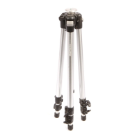
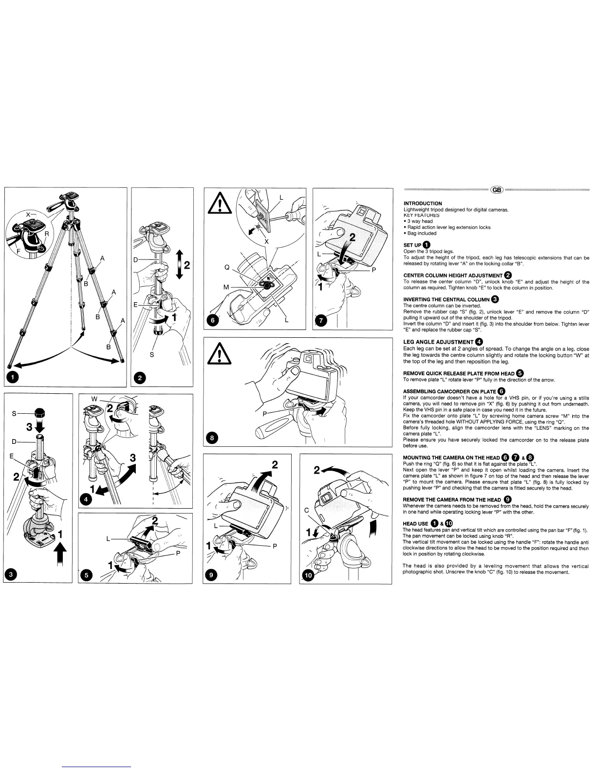
INTRODUCTION
lightweight
tripod designed for digital cameras.
KEY
FEATURES
·3
way head
• Rapid action lever leg extension locks
• Bag included
SETUPO
Open the 3 tripod legs.
To
adjust the height of the tripod, each leg has telescopic extensions that can be
released by rotating lever "A" on the locking collar "B".
CENTER COLUMN HEIGHT ADJUSTMENT e
To release the center column "D", unlock knob "E" and adjust the height
of
the
column as required. Tighten knob "E"
to
lock the column
in
position.
INVERTING THE CENTRAL
COLUMN
e
The centre column can be inverted.
Remove the rubber cap "S" (fig.
2),
unlock lever "E" and remove the column "D"
pulling it upward out
of
the shoulder
of
the tripod.
Invert the column "D" and insert it (fig.
3)
into the shoulder from below. Tighten lever
"E" and replace the rubber cap "S".
LEG
ANGLE ADJUSTMENT 0
Each leg can be set
at
2 angles
of
spread. To
change
the
angle on a leg,
close
the
leg
towards
the
centre
column
slightly and rotate
the
locking
button
"W"
at
the
top
of
the
leg and then reposition
the
leg.
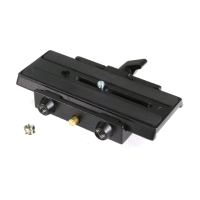
REMOVE QUICK RELEASE PLATE FROM HEAD 0
To remove plate "L" rotate lever "P" fully
in
the direction of the arrow.
ASSEMBLING CAMCORDER ON PLATE 0
If your camcorder
doesn't
have a hole
for
a VHS pin, or If you're using a stills
camera, you will need to remove pin "X" (fig.
6)
by pushing it out from underneath.
Keep the
VHS
pin
in
a safe place
in
case you need it
in
the future.
Fix the camcorder onto plate "L" by screwing home camera screw
"M"
into the
camera's threaded hole WITHOUT APPLYING FORCE, using the ring "Q".
Before fully locking, align the
camcorder
lens with the "LENS" marking on
the
camera plate "L".
Please ensure you have securely locked the camcorder
on
to
the release plate
before use.
MOUNTING THE CAMERA ON THE HEAD 0 G & e
Push the ring "Q" (fig.
6)
so that it
is
flat against the plate "L".
Next open the lever
"P"
and keep it open whilst loading the camera. Insert the
camera plate "L"
as
shown
in
figure 7 on top of the head and then release the lever
"P"
to
mount the camera. Please ensure that plate
"L"
(fig.
8)
is fUlly locked by
pushing lever "P" and checking that the camera
is
fitted securely to the head.
REMOVE THE CAMERA FROM THE HEAD 0
Whenever the camera needs to be removed from the head, hold the camera securely
in
one hand while operating locking lever "P" with the other.
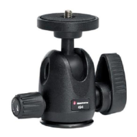
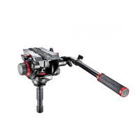
HEAD USE
O&~
The
head
features pan and vertical tilt which
are
controlled using the
pan
bar "F"
(fig.
1).
The pan movement can be locked using knob "R".
The vertical tilt movement can be locked using the handle "F": rotate the handle anti
clockwise directions
to
allow the head to be moved to the position required and then
lock
in
position by rotating clockwise.
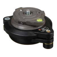
The head is also
provided
by
a
leveling
movement
that
allows
the
vertical
photographic shot. Unscrew the knob "C" (fig.
10)
to
release the movement.