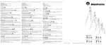
INTRODUCTION
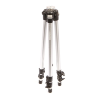
Lightweight tripod designed for digital cameras.
KEY
FEATURES
• Reversible centre column
• Rapid action lever leg extension locks
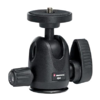
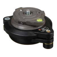
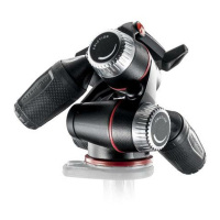
• Ball head
SETUPO
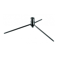
Open the 3 tripod legs.
To adjust the height
of
the tripod, each leg has telescopic extensions that can be
released by rotating lever "A"
on
the locking collar "B".
CENTRE COLUMN HEIGHT ADJUSTMENT e
To release the central column "C", unlock lever
"0"
and adjust the height
of
the
column
as
required. Tighten lever
"0"
to
lock
in
position.
INVERTING THE CENTRAL COLUMN e
The centre column can be inverted.
Remove the rubber cap "E" (fig.
2),
unlock lever
"0"
and remove the column "c"
pulling it upward out
of
the shoulder
of
the tripod.
Invert the column
"C"
and insert it (fig.
3)
into the shoulder from below. •
Tighten lever
"0"
and replace the rubber cap "E".
LEG
ANGLE
ADJUSTMENT
0
Each leg
can
be
set
at
2 angles
of
spread.
To
change
the
angle
on
a leg,
close
the
leg
towards
the
centre
column
slightly and rotate
the
locking
button
"W"
at
the
top
of
the
leg and
then
reposition
the
leg.
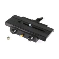
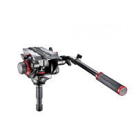
MODEL 7302YB
REMOVE QUICK RELEASE PLATE FROM HEAD 0
To remove plate "G" it is necessary
to
open the lever "H".
The lever "H" can not be opened whilst the safety lever "I"
is
in
closed position.
To remove the safety catch, rotate safety lever "I" fully
in
the direction of the arrow
and then rotate the lever
"H"
until peg "L" clicks up holding the open the lever "H".
ASSEMBLING CAMERA ON PLATE 0
Fix the camera
onto
plate
"G"
by screwing home camera screw
"M"
into the
camera's threaded hole WITHOUT APPLYING FORCE, using the ring
"Q"
1,\.
Before fully locking, align the camera with the plate "G" Please ensure you
~
have securely locked the camera on
to
the release plate before use
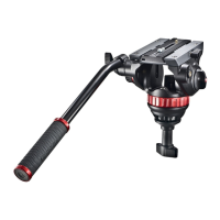
MOUNTING THE CAMERA ON THE HEAD 0 & Q
Push the ring
"Q"
so that it is flat against the plate "G"
A Insert the camera plate "G" (fig.
7)
on top
of
the head until locking lever
"H"
ill
clicks and closes.
Rotate the safety lever "I" fully
in
the direction
of
the arrow.
1,\.
Make sure
that
plate
"G"
(fig.
8)
is fully locked by pushing lever
"H"
and
~
checking that the camera
is
fitted securely to the head.
REMOVE THE CAMERA FROM THE HEAD
CD
Whenever the camera needs to be removed from the head, release the safety lever
A "I" and then hold the camera securely
in
one hand while operating locking
ill
lever
"H"
with the other.
USE~
&
CD
The lever "P" locks the movement of the head. To release the ball "N" for positioning
the camera, unlock lever "P" by rotating until free position. Once the desired position
is
achieved, lock the ball "N" by turning lever "P" fully
in
a clockwise direction.
."
Note: The angle
of
the lever on the ratchet knob "P" can be repositioned
as
required
without effecting the lock itself. Pull the lever outwards, rotate as required and
release and it will locate
in
the new position.
1,\.
The
heads are maintenance-free.
~
Do
not lubricate with any oil or silicon.

 Loading...