HYDRAULIC
64
547379EN
70 (08/03/2017)
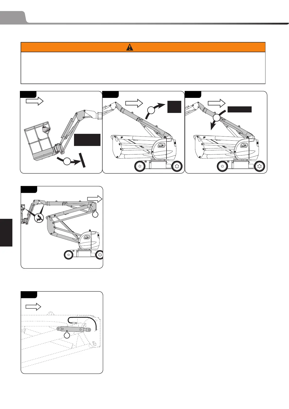
COMPENSATION/TILTING CYLINDER REMOVAL
WARNING
The hose connected to the compensation/tilting cylinders are pressurized EVEN WHEN STOPPED.
Before carrying out work to remove the cylinders, these hoses must be decompressed by following
the steps (I, 070 53), (II, 070 52) and (III, 070 54) because this line cannot be decompressed from the
distributor.
Compensating cylinder
- Raise arm 1/2 so that the intermediate hinge (1, 070 55) is raised
1m (39.37 in).
- Switch o the power supply.
- Secure the basket/jib assembly with a hoist and a sling:
3 without rotation cylinder (3D - JIB): 230 kg (507 lbs)
3 with rotation cylinder (3D - JIB): 267 kg (589 lbs)
- Open the right-hand turret cover.
- Remove the cylinder pivot pins (1, 070 56) and remove the cylinder
from the arms while leaving it connected to the hoses:
3 - 120 AETJL : 18 kg (40 lbs)
3 - 150 AETJC - 150 AETJL - 170 AETJL : 20 kg (44 lbs)
- Remove and plug the hoses connected to the cylinder and remove
the cylinder.
NOTE: This cylinder has no valves.
REFIT
- Follow the removal operations in reverse order.
- Purge the compensation/tilting circuit by repeating steps I to
VII several times (I & II, 070 59), (III & IV, 070 62), (V & VI, 070 61),
(VII, 070 60).
70 - 52
3 m
(118.11 in)
II
70 - 53
TO ITS FULL
EXTENT
I
70 - 54
1 cm (0.39 in)
III
70 - 55
1
70 - 56
1
 Loading...