3 - 20
C - EVERY 250 HOURS SERVICE
Carry out the operations described previously as well as the following operations.
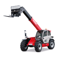
C1 - ALTERNATOR/CRANKSHAFT BELT TENSION
CHECK - ADJUST
- Open the I.C. engine bonnet.
- Unscrew the fastening screws 1 (fig. C1/1).
- Lay down the protective guard 2 (fig. C1/1).
- Check the belt for signs of wear and cracks and change if necessary (see: 3 -
MAINTENANCE: FILTERS CARTRIDGES AND BELTS).
- Check the belt tension between the pulleys of the crankshaft and of the alternator.
- Under a normal pressure exerted with the thumb (45 N), the tension should be
approximately 10 mm.
- Carry out adjustments if necessary.
- Untighten screws 3 (fig. C1/2) with two to three thread turns.
- Swivel the alternator assembly so as to obtain the belt tension required.
- Retighten screws 3 (fig. C1/2) (tightening torque 22 N.m).
- Put the protective guard back 2 (fig. C1/1).
If the alternator belt has to be changed, check the tension again after the first 20 hours of
operation.
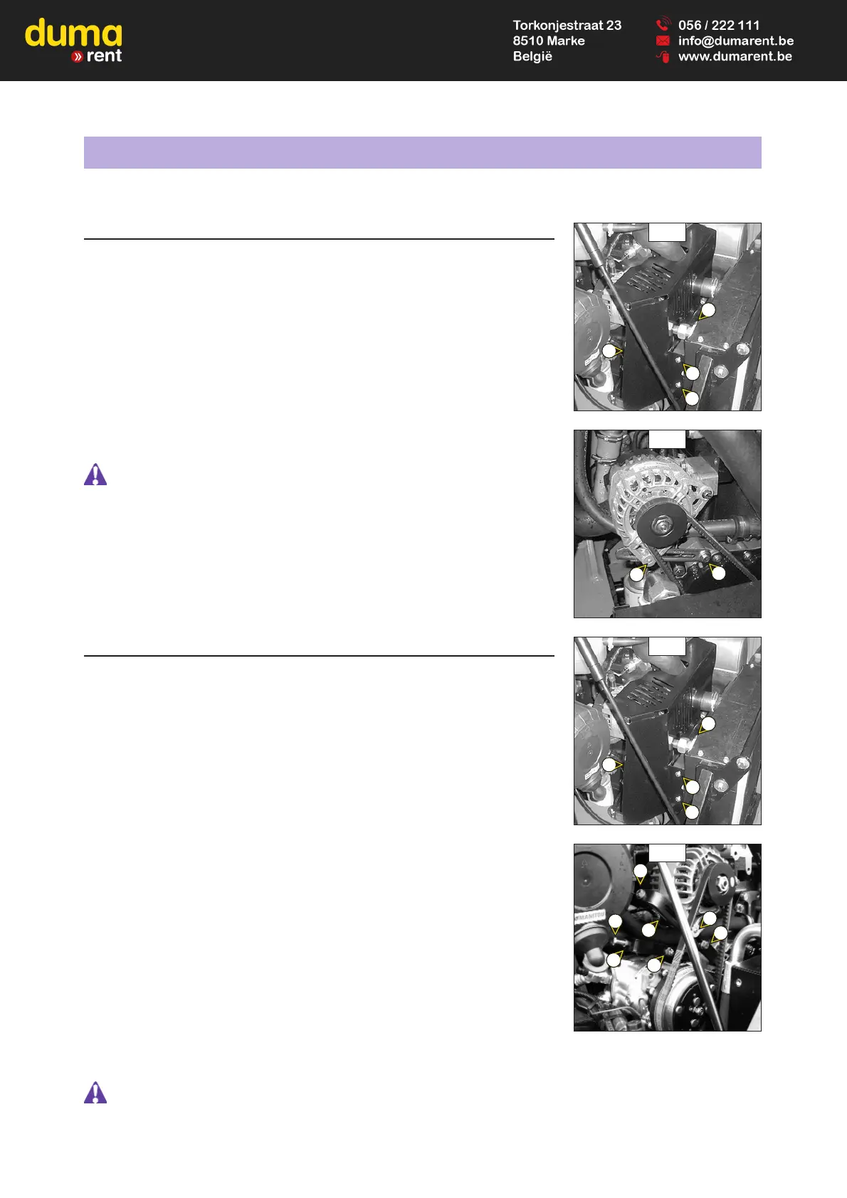
C2 - COMPRESSOR BELT TENSION (OPTION AIR CONDITIONING)
CHECK - ADJUST
MLT 523 Turbo Série B-E2
MLT 523 Turbo MONO-ULTRA Série B-E2
- Open the I.C. engine bonnet.
- Unscrew the fastening screws 1 (fig. C2/1).
- Lay down the protective guard 2 (fig. C2/1).
- Check the belts for signs of wear and cracks and change if necessary (see: 3 - MAINTENANCE:
FILTERS CARTRIDGES AND BELTS).
FAN/COMPRESSOR BELT
- Check the belt tension between the pulleys of the fan and the compressor.
- Under a normal pressure exerted with the thumb (45 N), the tension should be approximately
10 mm.
- Carry out adjustments if necessary.
- Unscrew the screws 3 (fig. C2/2) and the lock-nut 4 (fig. C2/2) by two to three turns.
- Tighten the screw 5 (fig. C2/2) so as to obtain the required belt tension.
- Retighten lock nut 4 (fig. C2/2).
- Retighten screws 3 (fig. C2/2).
COMPRESSOR/ALTERNATOR BELT.
- Check the belt tension between the pulleys of the compressor and the alternator.
- Under a normal pressure exerted with the thumb (45 N), the tension should be approximately
10 mm.
- Carry out adjustments if necessary.
- Unscrew the nut 6 (fig. C2/2) and the lock-nut 7 (fig. C2/2) by two to three turns.
- Tighten the screw 8 (fig. C2/2) so as to obtain the required belt tension.
- Retighten the nut 6 (fig. C2/2) and the lock-nut 7 (fig. C2/2).
- Put the protective guard back 2 (fig. C2/1).
If the compressor belt has to be changed, check the tension again after the first 20 hours of operation.
C2/2
8
5
6
7
4
3
3
C1/1
C1/2
1
1
1
2
C2/1
1
1
1
2
3
3