Sviluppo del cestello AERIAL JIB 2
(se equipaggiato)
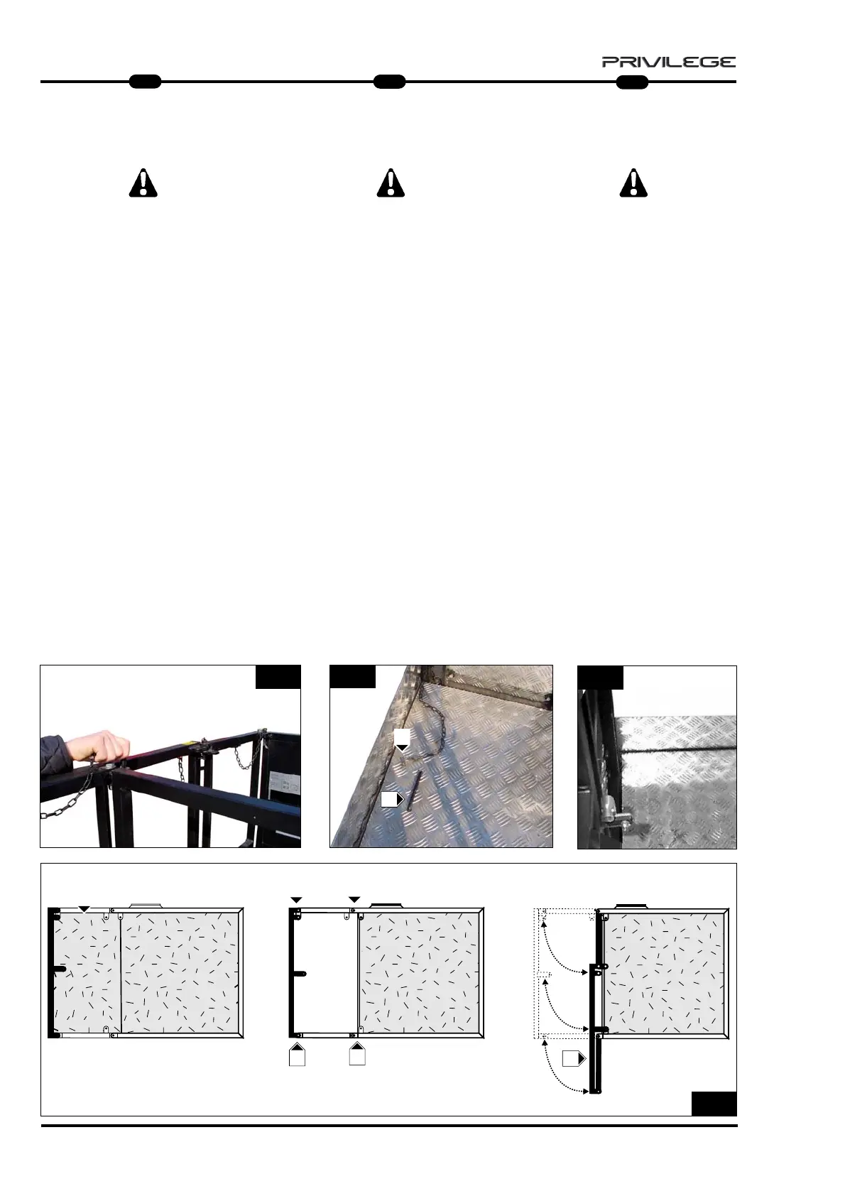
Apertura / chiusura (Fig. 53)
AL FINE DI EVITARE COLPI SULLA PEDA-
NA, VERIFICARE CHE SIA BEN ASSICU-
RATA GRAZIE AI BLOCCAGGIO
(Fig. 52).
Apertura
- Togliere le copiglie e togliere i perni di bloc-
caggio (Fig. 50) per ogni lato del fianco del
cestello).
- Ripiegare il lato mobile rif. L Fig. 53.
- Rimontare le copiglie ed i perni di bloccag-
gio rif. M (Fig. 53) per ogni lato del fianco
del cestello).
- Posare nella sua sede la pedana
rif. N (Fig. 53) con l’aiuto dell’impugna-
tura rif. P (Fig. 51) e bloccarla grazie
alla copiglia rif. Q (Fig. 51).
Chiusura
- Ripetere in modo inverso le operazioni di
apertura.
- Il cestello è pronto per essere alloggiato
nell’apposita sella.
28
IT
1
MRT 1850 - 2150 - 2540
53
N
M
51
50
52
L
Q
P
M
M
M
Längenentwicklung des Arbeitskorbs
AERIAL JIB 2 (wenn vorhanden)
Öffnung / Schließen (Abb. 53)
UM STÖßE AUF DAS TRITTBRETT ZU
VERHINDERN, SICHERSTELLEN, DASS
ES MIT DEN SPERRVORRICHTUNGEN 10
(Abb. 52) GUT BEFESTIGT IST.
Öffnen
- Die Splinte herausnahmen und die
Sperrbolzen (Abb. 50) auf jeder Seitenwand
der Arbeitsbühne entfernen).
- Die bewegliche Seite Bez. L Abb. 53
falten.
- Die Splinte und die Sperrbolzen Bez. M
(Abb. 53) auf jeder Seitenwand der
Arbeitsbühne wieder montieren).
- Das Trittbrett Bez. N (Abb. 53)
mit Hilfe des Handgriffs Bez. P
(Abb. 51) wieder einlegen und mit
dem Splint Bez. Q (Abb. 51) blockieren.
Schließen
- Die Vorgänge zum Öffnen in der
umgekehrten Reihenfolge wiederholen.
- Die Arbeitsbühne ist nun bereit, auf
ihrem Sattel aufmontiert zu werden.
Length of the AERIAL JIB 2 basket
(if fitted)
Opening / closing (Fig. 53)
IN ORDER TO AVOID KNOCKING ON THE
PLATFORM MAKE SURE IT IS PROPERLY
SECURED BY MEANS OF LOCK
(Fig. 52).
Opening
- Remove the split pins and the locking pins
(Fig. 50) for each side of the basket.
- Fold back the mobil side ref. L Fig. 53.
- Mountain again the split pins and the locking
pins for each side of the basket
ref. M Fig. 53.
- Place in its seat the board the ref. N Fig. 53
with the help of the handle ref. P Fig. 51
and locki it with the split pin ref. Q Fig. 51.
Closing
- Repeat the opening operations inversely
- The basket is ready to be placed in the right
support.
EN
DE