EasyManua.ls Logo

Manitowoc CNF202A - User Manual

Manitowoc CNF202A
116 pages
To Next Page IconTo Next Page
Loading...
Part Number 000015432 4/18
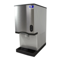
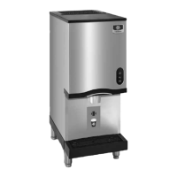
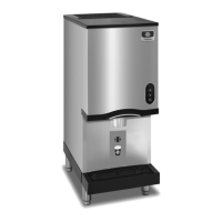
Countertop Nugget
Ice Machines
CNF201 & CNF202
Technician’s Handbook

Table of Contents

Question and Answer IconNeed help?

Do you have a question about the Manitowoc CNF202A and is the answer not in the manual?

Manitowoc CNF202A Specifications

General IconGeneral
ModelCNF202A
Ice TypeNugget
Condenser TypeAir-cooled
RefrigerantR-404A
Power Supply115V/60Hz/1Ph
Water Connection3/8 inch

Summary

Safety Notices

Installation

Location of Ice Machine

Lists criteria for selecting an appropriate indoor location for the ice machine.

Electrical Service

Ice Machine Head Section Water Supply and Drains

Operation

Ice Making Sequence of Operation

Explains the step-by-step process of ice production, from start-up to freeze cycle.

Maintenance

Manitowoc’s Cleaning Technology

Explains the automated cleaning cycle and periodic maintenance requirements for ice machines.

Heavily Scaled Cleaning Procedure

Details the procedure for cleaning machines with significant scale buildup or noises.

Cleaning;Sanitizing Procedure

Outlines the recommended minimum six-month cleaning and sanitizing schedule for the unit.

Cleaning Procedure

Sanitizing Procedure

Component Disassembly for Cleaning and Sanitizing

CLEANING THE CONDENSER

Troubleshooting

SafeGuard Feature

Explains the ice machine's safety features that stop operation on potential failure.

Standby Mode

Details the standby mode operation after a failure occurs, including auto-restart.

SafeGuard Indicator Lights

Explains the meaning of indicator lights during SafeGuard mode for diagnostics.

Reset Procedure

SafeGuards

NO WATER

Explains the operation when the water sensing switch opens for an extended period.

NO ICE PRODUCTION

Ice Machine Will Not Run Diagnostics

Refrigeration Diagnostics

ANALYZING DISCHARGE PRESSURE

Discharge Pressure Low Checklist

ANALYZING SUCTION PRESSURE

Suction Pressure Low Checklist

Component Check Procedures

MAIN FUSE

Function, specifications, and testing procedure for the main fuse.

ICE;OFF;CLEAN TOGGLE SWITCH

FLOAT SWITCH

ICE DAMPER AND HALL EFFECT SWITCHES

Hall Effect Switch Diagnostics

SWITCH FAILS CLOSED

SELECTOR SWITCH

TOUCHLESS SENSOR ACTIVATED

HIGH PRESSURE CUTOUT (HPCO) CONTROL

FAN CYCLE CONTROL

LOW PRESSURE CUTOUT (LPCO) CONTROL

COMPRESSOR ELECTRICAL DIAGNOSTICS

COMPRESSOR DRAWING HIGH AMPS

Explains amperage draw issues and diagnosing capacitors for compressor starting.

Compressor Drawing Locked Rotor

DIAGNOSING START COMPONENTS

Relay Operation Check

Refrigerant Recovery;Evacuation

NORMAL SELF-CONTAINED PROCEDURES

Guidelines for capturing refrigerant using recovery equipment without releasing it to atmosphere.

Recovery;Evacuation Procedures

Charging Procedures

System Contamination Clean-Up

CLEANUP PROCEDURE

Severe System Contamination

REPLACING PRESSURE CONTROLS WITHOUT REMOVING REFRIGERANT CHARGE

Component Specifications

Related product manuals