3-8 Published 4-23-2018 Control # 239-11
OPERATING CONTROLS & PROCEDURES NBT40 SERIES OPERATOR MANUAL
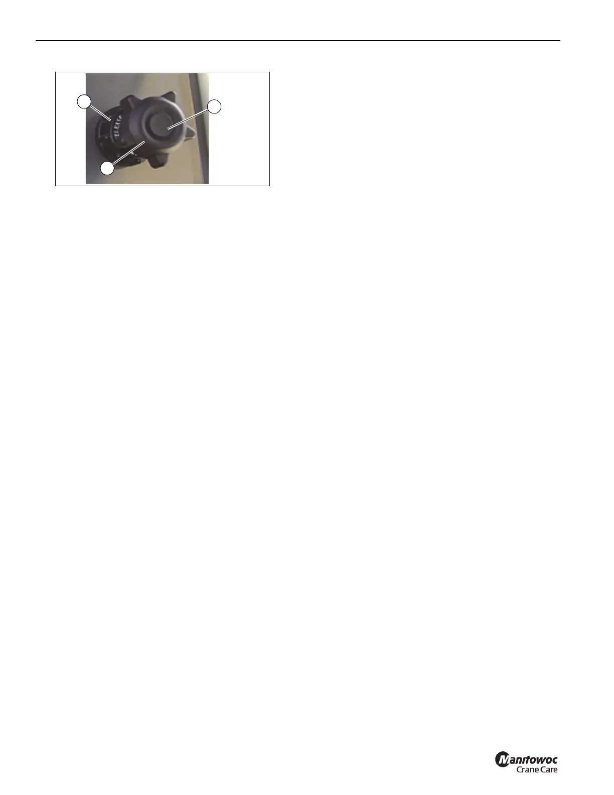
Emergency Stop Switch
The crane emergency stop switch (12, Figure 3-3) is located
on the cab console and is used to shut down the truck
engine. Push the red button in to shut down the engine,
rotate the knob and pull out to resume normal operation.
Crane Ignition Switch
The crane ignition switch (13, Figure 3-3) is located on the
crane cab console and controls the truck engine and crane
cab power. The igniton switch has four positions. OFF shuts
down engine and cab power, ON activates truck engine
ignition as well as all cab power, ACC is crane cab power
and Start is truck engine start.
The truck ignition key must be OFF before the truck engine
can be started from the crane cab.
Aux Hoist Speed (Optional)
The auxiliary hoist speed selector switch (15, Figure 3-3) is
located on the left seat armrest. It is a three position switch
(on-on-on), placarded as rabbit (fast) hoist motor speed and
turtle (slow) hoist motor speed.
Auxiliary Hoist Minimum Wrap Indicator
(Optional)
When the auxiliary hoist is down to the last cable wrap the
minimum wrap indicator (16, Figure 3-3) will flash
intermittent and the minimum wrap buzzer (2, Figure 3-5) will
sound intermittently.
When the amount of cable left on the hoist reaches the
minimum wrap; the indicator light will be constant, the buzzer
will be constant and the hoist will be disabled by the
minimum wrap sensor system.
AC/Heater Vent
The cab has air conditioner and heating vents (17,
Figure 3-3), located on the control panel, behind the panel.
and to the left of the operator.
Receptacle
This 12 volt accessory outlet (18, Figure 3-3) is located on
the lower part of the front control panel and is designed to
mate with most 12 volt adapter plugs.
Radio Remote Switch (Optional)
The radio remote switch (19, Figure 3-4) is used to enable
the radio remote controls. The crane function power switch,
crane ignition (13) and truck igniton must all be OFF before
the crane can be operated with a radio remote control.
Crane Power Switch
The crane function power switch (20, Figure 3-3) is located
on the right overhead console. The switch has two positions:
OFF takes all power from the joy stick controllers on the arm
rest, cab outrigger, and from the swing brake unlock
(assuring the brake stays locked). The OFF position
prevents inadvertent operation of these functions and
assures the swing brake is set when the crane is not
powered. The ON position will restore power to the joy stick
controllers, the swing brake and the cab O/R hand controller.
Boom Work Light Switch (Optional)
The work light switch (21, Figure 3-3) is a two position rocker
switch, ON and OFF, located on the right overhead console.
It turns the cab outside working lights on.
Cab Work Light Switch
The work light switch (22, Figure 3-3) is a two position rocker
switch, ON and OFF, located on the right overhead console.
It turns on custom mounted boom lights.
Skylight Wiper Switch
The skylight wiper switch (23, Figure 3-3) is located in the
overhead console. This is Hi - Lo toggle type switch with 6
intermitting positions, intermitting timing is 2-15 seconds.
Windshield Wiper Switch
The windshield wiper switch (24, Figure 3-3) is located in the
overhead console. This is Hi - Lo toggle type switch with 6
intermitting positions, intermitting timing is 2-15 seconds,
wiper washer timing is 3 seconds.
Crane Cab Climate Controls
The cab climate controls (25, 26, 27, Figure 3-3) are used to
adjust the heating and air conditioning for operator comfort.
360°Swinglock Pedal (Optional)
The swinglock pedal (28) is located on the left side of the
crane cab floor. Apply the pedal to lock the turret, release the
pedal to unlock the turret.
 Loading...


