L
lwhiteheadAug 9, 2025
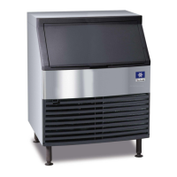
What to do if my Manitowoc Ice Maker runs but no ice is produced?
- SsmithcharlesAug 9, 2025
If your Manitowoc Ice Maker is running but not producing ice, there might be several reasons: * Ensure the ice machine has a water supply. * Verify the incoming water pressure is within the range of 20-80 psi (1.4-5.5 bar). * Check if the spray nozzle is blocked with mineral buildup; if so, clean and sanitize the ice machine. * Confirm the ambient temperature is between 50°F and 110°F (10°C and 43°C). * Refer to thermistor diagnostics.