Do you have a question about the Marantz CD17/K1G and is the answer not in the manual?
Procedures for ordering Marantz replacement parts, including required information.
Details on audio parameters like channels, sampling frequency, quantization, error correction, and wow/flutter.
Covers laser type, wavelength, and related optical pickup parameters.
Specifies frequency range, dynamic range, S/N ratio, channel separation, THD, and output levels.
Details input voltage, frequency, and power consumption of the unit.
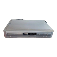
Provides physical dimensions and net weight of the CD player unit.
Lists operating temperature and humidity ranges for the device.
Lists all accessories provided with the unit, such as remote control, batteries, and cables.
Guidelines for soldering and handling electronic components, especially surface-mount devices.
Instructions and tips for safely removing and installing internal components.
Important considerations and correct methods for soldering to prevent damage and ensure reliability.
Visual examples demonstrating correct soldering techniques for components.
Procedures for entering, navigating between modes, and exiting the service mode.
Details on specific operations within the service mode and a list of error codes for troubleshooting.
Detailed pin assignment and description for the SAA7372GP microprocessor.
Pin assignment and function description for the TDA1302T component.
Pin details for the TDA7073A ICs used in the audio circuitry.
Pin assignment and function description for the LC89170M IC.
Overall schematic illustrating the functional blocks of the CD player system.
Reference list of flag numbers and their corresponding meanings or functions used in the system.
Detailed electrical schematic diagram for the Servo PCB.
Detailed electrical schematic diagram for the Main PCB.
Information on how to recall default settings for last memory functions, typically via STOP button.
Explanation of priority settings for text display when using CD-TEXT discs.
Description of how time is displayed, specifically elapsed play time.
Information on the default setting for the audio filter position.
Diagram illustrating component placement on the PV16 Printed Circuit Board.
Diagram illustrating component placement on the PH16 Printed Circuit Board.
Diagram illustrating component placement on the PY16 Printed Circuit Board.
Visual exploded view showing the assembly of the CD player's main components.
Introduction to the parts list, explaining symbols and part naming conventions.
Explanation of resistor part number coding and examples of resistance values.
Explanation of capacitor part number coding and examples of capacity values.
Glossary of common abbreviations and symbols used throughout the electrical parts list.
Essential safety warnings regarding part replacement and the necessity of using original parts.