Do you have a question about the Marantz CD-67 and is the answer not in the manual?
Details the procedure and required information for ordering Marantz replacement parts.
Specifies audio performance parameters such as channels, sampling frequency, and output levels.
Details the optical system, including laser type and wavelength.
Provides frequency range, dynamic range, S/N ratio, and distortion.
Specifies power supply voltage and power consumption for different models.
Details physical dimensions, net weight, operating temperature, and humidity.
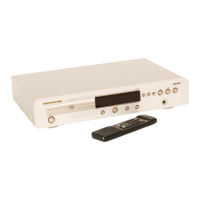
Lists accessories provided with the unit, such as remote control and batteries.
Warns about invisible laser radiation and advises avoiding exposure when the unit is open.
Describes the key combinations required to enter the service mode.
Explains the functions of different service modes (0-3) and key operations within them.
Lists potential error codes detected during operation and their corresponding meanings.
Details the procedure for cancelling the service mode.
Provides a detailed pinout diagram and function description for the MN187164 microprocessor.
Illustrates the main functional blocks and their interconnections within the CD player.
Details the function of each pin for the SAA7372GP digital decoding IC with RAM.
Presents the overall block diagram of the CD player's functional modules.
Provides pinout and function details for the SM5872BS digital filter and D/A converter IC.
Illustrates the component placement and routing on the main printed circuit board.
Illustrates the component placement and routing on the servo printed circuit board.
Presents the detailed circuit schematic for the power audio and digital sections of the player.
Presents the detailed circuit schematic for the servo control section.
Provides DC voltage measurements for key points on the MN187164 microprocessor.
Details the circuit and connections for the front panel controls and display.
Details the function and pinout for the QF02 PS94D IC.
Illustrates common signal waveforms for various service positions and modes.
Details transformer specifications for different versions and the voltage selector mechanism.
Presents the circuit diagrams for the main power supply and voltage regulation.
Provides safety notes regarding electrical shock hazards and component substitution.
Presents the circuit diagrams for the audio amplifier and output stages.
Details voltage checks for various power supply rails across different model versions.
Illustrates signal waveforms and reiterates safety precautions for servicing.
Illustrates the component layout and connections on the front PCB.
Presents the circuit diagram for the headphone output stage.
Illustrates signal waveforms and reiterates safety precautions for servicing.
Provides an exploded view of the CD mechanism assembly.
Provides an exploded view of the main chassis and enclosure components.
Lists specific part numbers, colors, descriptions, and European/other region part numbers.
Details how to convert the unit to a different power source voltage.
Explains the coding system for common fixed and fusible resistors.
Explains the coding system for common ceramic and electrolytic capacitors.
Provides a list of common abbreviations and marks used throughout the service manual.
Warns about fire or electrical shock hazards and the importance of using original parts.
Lists miscellaneous parts such as fuses, switches, and crystals for the P116 PCB.
Details capacitors and semiconductors used on the P126 PCB.
Lists components and parts for the P136 circuit board.
Lists common electrolytic and film capacitors used on the P116 PCB.
Lists semiconductors such as diodes and ICs used on the P116 PCB.
Details ceramic and film capacitors used on the P136 PCB.
Lists semiconductors such as diodes and ICs used on the P136 PCB.
Lists ceramic capacitors used on the PY16 front circuit board.
Lists diodes used on the PY16 front circuit board.
Details common resistors used on the PY16 front circuit board.
Lists push switches and display units for the PY16 front circuit board.
| Type | CD Player |
|---|---|
| Dynamic Range | 96dB |
| Channel Separation | 100dB |
| Line Output | 2.0V RMS |
| Digital Outputs | Coaxial, Optical |
| Disc Format | CD |
| Digital Converter | 1-bit DAC |
| CD Mechanism | CDM12.1 |