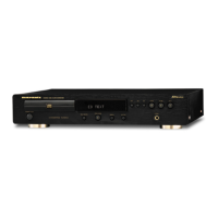
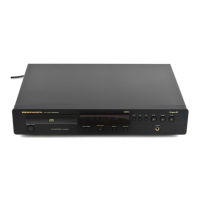
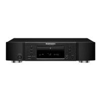
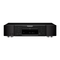
EasyManua.ls Logo

Marantz CD6000OSE User Manual

Marantz CD6000OSE
36 pages
To Next Page IconTo Next Page
Page #1 background imageLoading...
Page #1 background image
Service
Manual
CD6000K/N1B/T1B
/N1G/T1G
R
CD6000 KI
255W855020 ACT
3120 785 22570
First Issue:2001.04
Printed in The Netherlands
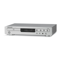
CD6000 KI
CD6000 KI
CD Player
REMARK : This service manual explains the electrical differences between the
CD6000K/N1B/T1B/N1G/T1G (KI version) and CD6000F/N1B/T1B/N1G/T1G
(OSE version).
All other information is described in the service manual of the model
CD6000F/N1B/T1B/N1G/T1G (Code number : 3120 785 00060). The dispatch of
the parts for after sales service has to be referred to these service manuals, with
the first priority.
For this reason, please use these service manuals with referring to the model
CD6000 OSE service manual without fail.
The CD6000 KI is equal to the CD6000 OSE except the following electrical
changes (mechanical changes are not listed):
Position No. Service code Description
2131, 2132 9965 000 08117 3300uF 25V
2115, 2116, 4822 124 80123 220uF 16V Silmic
2223,2224,
2225,2226
2311, 2312, 4822 124 80958 470uF 16V Silmic
2316, 2317
5110 4822 146 10377 230V Transformer
3249, 3250, -- Short circuited
3251,3252,
3711, 3712,
3713, 3714
Main PCB
Question and Answer IconNeed help?

Do you have a question about the Marantz CD6000OSE and is the answer not in the manual?

Marantz CD6000OSE Specifications

General IconGeneral
TypeCD Player
Disc formatsCD, CD-R, CD-RW
Frequency Response2 Hz - 20 kHz
Signal-to-Noise Ratio110 dB
Total Harmonic Distortion0.0025%
Dimensions440 x 105 x 320 mm
Weight4.2 kg
Dynamic range100 dB
Channel separation100 dB
Output Voltage2.0 V

Summary

Marantz Service and Safety

Marantz Design and Service Philosophy

Information on Marantz's commitment to quality and original parts.

Ordering Marantz Parts

Guidelines for requesting replacement parts via mail or fax.

Critical Safety Test Procedures

Essential safety test for leakage current before returning serviced unit.

1. Technical Specifications

Audio and Optical Characteristics

Detailed specs for audio output, frequency range, S/N, and laser system.

Power Supply, Cabinet, and Accessories

Specifications for power requirements, physical dimensions, weight, and included accessories.

2. Servicing Hints

General Repair and Handling Precautions

Guidelines for general repair, component handling, and ESD protection.

Dismounting, Mounting, and Soldering Techniques

Procedures and examples for component removal, installation, and soldering.

3. Service Tools

Essential Service Tools List

List of specific tools, discs, and drivers required for maintenance.

Safety Information and Warnings

ESD Protection Measures

Critical information on electrostatic discharge prevention and necessary equipment.

Laser Product Safety

Warnings regarding invisible laser radiation and safe operating practices.

General Safety Regulations

Requirements for maintaining original condition and performing safety checks.

4. Service Mode

Entering and Using Service Mode

Step-by-step guide to accessing and navigating through the unit's service modes.

Service Mode Functions and Error Codes

Description of operational modes, segment tests, and error code interpretation.

5. Microprocessor and IC Data

Integrated Circuit Specifications

Comprehensive data and listings for microprocessors and integrated circuits used in the unit.

6. Block Diagram

System Signal Flow Diagram

Visual representation of the main functional blocks and signal paths within the CD player.

7. Wiring Diagram

Inter-PCB Connection Schematics

Diagram illustrating the wiring and connections between various printed circuit boards.

8. Schematic Diagrams and Parts Location

Audio Amplifier PCB Schematic and Layout

Detailed schematic and component placement for the audio amplifier board.

Audio Amplifier PCB Visual Guides

Audio Amplifier PCB Component Side View

Illustration of component placement on the top side of the audio amplifier board.

Audio Amplifier PCB Copper Side View

Illustration of the copper trace layout on the bottom side of the audio amplifier board.

PCB Schematics and Layout Details

Audio Amplifier Servo Part Schematic

Schematic for the servo section of the audio amplifier board.

Control PCB Schematic and Layout

Schematic diagram and component layout for the control board.

Control and HDAM PCB Visuals

Control PCB Component Side View

Illustration of component placement on the top side of the control board.

HDAM PCB Component Side View

Illustration of component placement on the top side of the HDAM board.

HDAM PCB Schematic

HDAM PCB Component Configuration

Detailed schematic of the HDAM board showing transistors and their connections.

Front PCB Schematics and Views

Front PCB Schematic Diagram

Schematic diagram for the front panel interface and controls.

Front PCB Component Layout

Illustration of component placement on the top side of the front panel board.

HF Amplifier PCB Details

HF Amplifier PCB Schematic

Schematic diagram for the high-frequency amplifier section.

HF Amplifier PCB Visual Layouts

Illustrations of component placement and copper traces on the HF amplifier board.

Other PCB Schematics

Headphone Jack and Optical Out PCBs

Schematics and component views for the headphone jack and optical output boards.

9. Exploded View and Parts List

CD Loader Exploded Assembly Diagram

Diagram illustrating the physical arrangement of CD loader components.

Parts List for CD Loader Exploded View

List of parts corresponding to the exploded view diagram.

10. Electrical Parts List

Audio Amplifier Component List

Detailed list of electronic components used on the audio amplifier board.

General Electrical Component List

Comprehensive list of various electrical parts used throughout the unit.

Related product manuals