Do you have a question about the Marantz CD5005 and is the answer not in the manual?
Procedures for leakage current and resistance checks before returning the set.
Important safety guidelines for handling, disassembly, and parts replacement.
How safety-critical parts are indicated in diagrams and parts lists.
Precautions for Class 1 laser products and avoiding radiation exposure.
Steps to initialize the unit after replacing major components like the microcomputer.
Method to protect the LD during soldering and circuit connection/removal.
Guidelines for handling the laser pick-up to prevent dust and damage.
Safety and environmental considerations during mechanism assembly and adjustment.
Procedures to diagnose a defective laser pick-up using RFEQO waveform and laser current.
Procedure to short the laser pick-up and disconnect wires/FFC.
Modes for cold start initialization and CD mechanism tests.
Steps for checking LD ON, FOCUS ON, CLV ON, TRACKING ON, and SUB CODE.
Procedure to display, measure, and store the laser drive current.
Steps for performing normal heat run tests, including track playback and repetition counting.
List and explanation of various error codes (E1-00 to E9-01) encountered during tests.
Guidelines for checking software content after replacing the microprocessor or Flash ROM.
Instructions on connecting the PC using SPK-581 and FFC for firmware updates.
Steps to connect the SPK-581, PC, and unit for the update process.
How to launch the Boot Tool software and select the COM port.
Confirming successful communication, indicated by "Connected" message.
Procedure to select and load the "OnBoard_M330.s32" RAM file.
Procedure to select and load the "CD5005_XXXXX.s32" flash file.
Clicking the Start button to begin the firmware flashing process.
Action upon successful update ("OK" message) and disconnecting the jig.
Steps to initialize the unit after the firmware update is complete.
Procedure to check the updated firmware version.
Initial troubleshooting steps for a unit that does not power on, checking connectors and indicators.
Detailed checks for power supply voltages, relays, and rectifying circuits.
Checks for filament output voltage and input voltages to the FL driver circuit.
Verifying PCB connections, resistances, and the FLD component itself.
Visual representation of control waveforms for the FL display.
Steps to diagnose why the remote control is not functioning, checking power and sensor signals.
Verifying PCB connectors and DAC IC digital input signals.
Checking DAC power supply, analog signal output, and mute signals.
Shows eye-pattern waveforms for CD, CD-R, and CD-RW disc playback.
Illustrates the signal path from CD DSP to DAC and audio outputs.
Shows signal flows for MCU, display, EEPROM, and power management.
Diagram showing power supply voltages (+5V, +3.3V, +12V, -12V, +7V, +42V) distribution.
Details of the TMPM330FYFG microcontroller, including pin functions.
Detailed explanation of pin functions for the CS4398 DAC IC.
| CD changer | No |
|---|---|
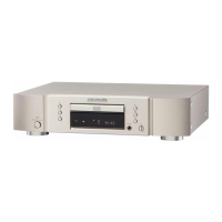
| Device type | HiFi CD player |
| MP3 playback | Yes |
| Product color | Gold, Silver |
| Number of decks | 1 deck(s) |
| Disc loading type | Tray |
| Frequency range | 20 - 20000 Hz |
| Audio formats supported | AAC, MP3, WMA |
| Signal-to-Noise Ratio (SNR) | 110 dB |
| Total Harmonic Distortion (THD) | 0.002 % |
| Headphone outputs | 1 |
| Headphone connectivity | 6.3 mm |
| Power consumption (standby) | 0.3 W |
| Power consumption (typical) | 14 W |
| Volume control | Rotary |
| Cables included | AC |
| Playback disc formats | CD audio |
| Remote control type | RC002PMCD |
| Depth | 338 mm |
|---|---|
| Width | 440 mm |
| Height | 105 mm |
| Weight | 5000 g |