28
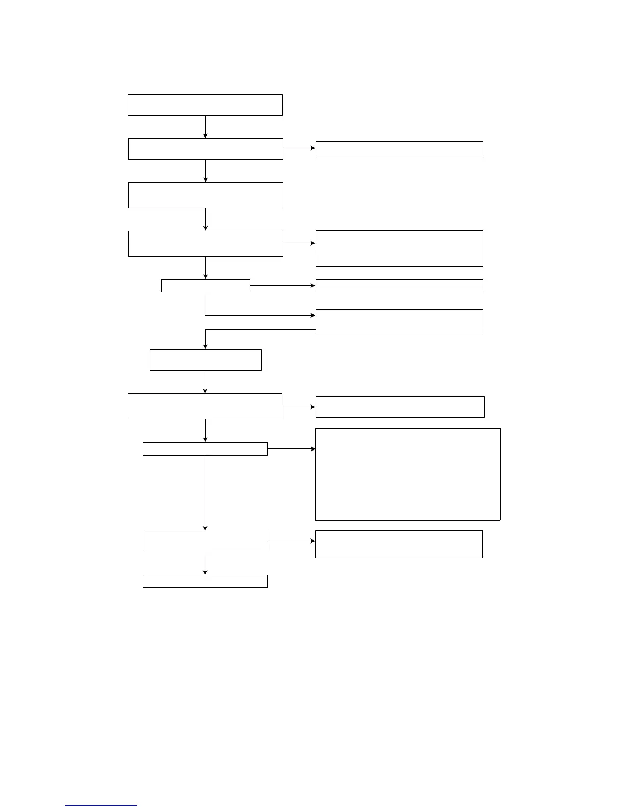
7.4.2 Troubleshooting P816
Figure 7-26
YES
OK
Connect the mains inlet to a mains
isolated variac
Check the functionality of the following components :
F820, R819, C820, L820, D802, C821
Check Vcc on pin 1 Q810
Vcc = 12V...... 16V
Is power supply ticking?
Check start circuit and Vcc supply:
R823, R834, C829, D829, R829, R811, C811
Replace Q810
Power supply OK
Power supply unit OK
OK
OK
OK
OK
OK
Check the path of the other faulty voltage(s)
Power supply is OK
Check : - CDR main board
- Display assy
Check DC voltages
+5V, +12V, -8V, VFTD (-34V),VDC1-VDC2 (4V1)
Check the +5V and +12V
Disconnect power supply unit from CDR main board
Connect dummy load resistors 10W,
15 ohm at +5V, +12V and ground
Check DC voltages
These voltages might be somewhat higher than specified
+5V, +12V, -8V, VFTD, VDC1-VDC2
OK
+5V : check D856, C857, L856, C859
+12V : check D866, C867, L867, R866, D868, C869
±1.41 x Vin AC
Turn input voltage up and check voltage across C821,
this voltage should be
OK
OK
Check fuse F820 and
replace if necessary
OK
NO
Load on secondary output
Overvoltage protection : L832, D814, C814, R814, R815, R816
Oscillator voltage on pin 10 of Q810 :
check C802, R810 replace Q810
Drive circuit : gate voltage of MOSFET Q825
components R812, R813, C813, R825
Regulation circuit
- Measure voltage on pin 6 of Q810 with oscilloscope
- If > 2.5V check the regulation circuit : Q810, D881
R881- R885, C881, C882, R804 - R806, R809, C804, C809
Check :
OK
CL 96532076_037.eps
290799
 Loading...