18
Voltage
Reference
Modulator
∆ Σ
Modulator
∆ Σ
Digital Decimation
Filter
Serial Output
Interface
Clock Divider
5 4 2 13 24 22 17 15 23 18 19 20
21
3
6
7
1
2
VREF
AINL+
AINL -
AINR+
AINR -
AGND VA VD DGND VB CMODE MCLK SMODE2 SCLK LRCK FSYNC
S DATA
SMODE1
PD HPFE TST1 TST2 TST3 TST4
16 9 8 10 11 14
Test pin Should be left floating. (Pull- down pin)
No. Pin Name I/O PIN / FUNCTION
1 AINR+
I
Right channel analog positive input pin
2 AINR-
I
Right channel analog negative input pin
3 VREF
O
Voltage Reference output pin (VA-2.6V)
Normally connected to VA with a 0.1uF ceramic capacitor in
parallel with a 10uF electrolytic capacitor.
4 VA Analog section Analog Power Supply, +5V
5 AGND Analog section Analog Ground
6 AlNL+
I
Left channel analog positive input pin
7 AINL-
I
Left channel analog negative input pin
8 TST1
Test pin Should be left floating. (Pull- down pin)
Test pin Should be left floating. (Pull- down pin)
Test pin Should be left floating. (Pull- down pin)
10 TST2
11 TST3
14 TST4
9 HPFE
I
High Pass Filter Enable pin (Pull- up pin)
"H": ON
"H": OFF
12 VD Digital section Digital Power Supply pin, +5V
13 DGND Digital section Digital Ground pin
16 PD
I
Power Down pin
"L" brings the device into power-down mode. Must be done
once after power-on.
17 MCLK I Master Clock input pin
CMODE="H" : 384fs
CMODE="L" : 256fs
18 SCLK I/O Serial Data Clock pin
Data is clocked out at the falling edge of SCLK.
Slave mode: 64fs clock is input usually.
Master mode: SCLK outputs a 64fs clock.
SCLK stays low during the power-down mode(PD="L").
19 LRCK I/O L/R Channel Clock Select pin
Slave mode: An fs clock is fed to this LRCK pin.
Master mode: LRCK output an fs clock.
LRCK goes "H" at SMODE2="L" and "L" at SMODE2="H"
during reset when SMODE1 "H".
20 FSYNC I/O Frame Synchronization Signal pin
S!ave mode: When "H", data bits are clocked out on SDATA.
As I
2
S slave mode ignores FSYNC It should hold "L" or
"H".
Master mode: FSYNC outputs 2fs clock.
Stay low during the power-down mode(PD="L") .
21 SDATA O Serial Data Output pin
Data are output with MSB first, in 2's complement format.
After 20 bits are output it turns to "L". It also remains "L" at a
power- down mode(PD="L").
22 CMODE I Master Clock Selection pin
"L": MCLK=256fs
"H": MCLK=384fs
23 SMODE1 I Serial Interface Mode Select pin
15 SMODE2 I Defines the directions of LRCK, SCLK and FSYNC pins and
Output Data Format. SMODE2 is pull- down pin.
SMODE1 SMODE2 MODE LRCK
L L Slave mode: MSB justified : H/L
H L Master mode Similar to I
2
S : H/L
L H Slave mode: I
2
S : L/H
H H Master mode: I
2
S : L/H
24 VB
Substrate Power Supply, +5V
The Audio board for the CDR631 is a full high performance
AD/DA panel, acting as an interface to the outside world. Key
components are DS1807, ADC AK5351 and DAC AK4393.
Description
The via BALANCE in connected anolog-in L and R signals are
pre-amplified by opamp Q761-Q763, and the via UNBALANCE
in connected anolog-in L and R signals are pre-amplified by
opamp Q705, Q706, these signals is selected by Analog SW
Q701 after which they are presented to an adjustable amplifier
made out of DS1807 and opamp Q703 - Q708. The level of the
incoming. Analog signal is adjusted by means of control lines
"I
2
C" coming from the DASP on the CDR main board and
switching the mux/demux. The anolog signal is then presented
to the A/D converter A5351 (QA01) where they are converted
from analog to I
2
S-bus data format. The I
2
S-bus is connected
via connector J601 and flex to the DASP on the CDR main
board. The ADC uses the CL11-clock (11.2896 MHz), coming
from the DASP on the CDR main board.
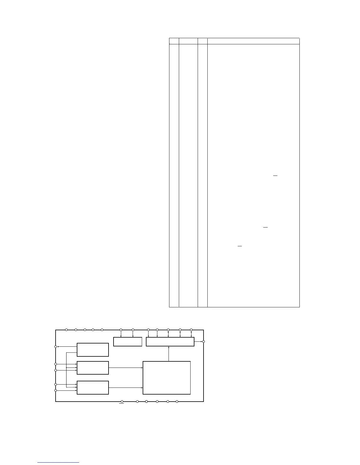
ADC AK5351
Description
The AK5351 is a stereo, 20-bit oversampling ADC based on
Sigma Delta technology intended primarily for digital audio
bandwith applications. It supports the I2S-bus data format. The
device can be used in either slave or master mode. In this
application it is used in slave mode receiving it's clock from the
DASP on the CDR main board.
Block diagram
7.2 Audio Board
7.2.1 Analog-in path
Figure 7-10
Figure 7-11
Pin description
 Loading...