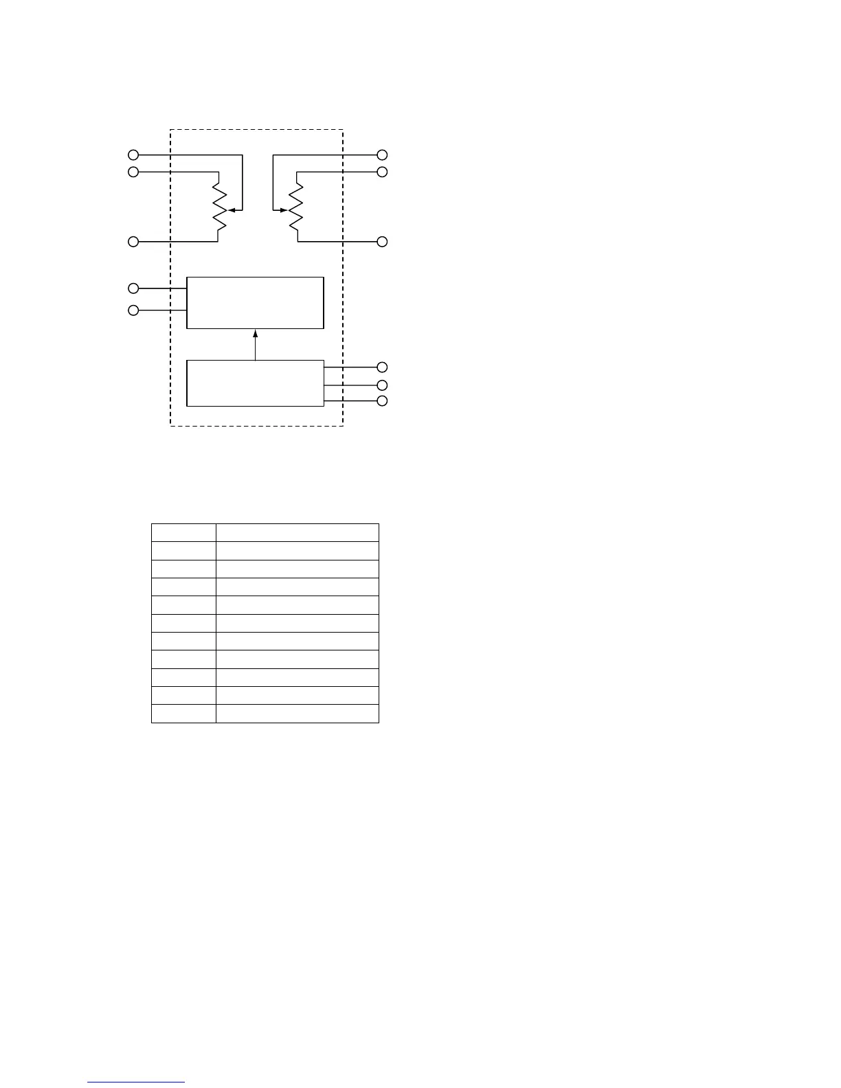
EasyManuals Logo

Marantz CDR631 Service Manual

Marantz CDR631
45 pages
To Next Page IconTo Next Page
To Previous Page IconTo Previous Page
Page #21 background imageLoading...
Page #21 background image
19
WO
HO
LO
SCL
SDA
A0
A1
A2
L1
H1
W1
Control Logic
Address Logic
Figure 7-12
Figure 7-14
Pin description
PIN DESCIPTION
L0, L1 Low End of Resistor
H0, H1 High End of Resistor
W0,W1 Wiper Terminal of Resistor
VCC 3V/5V Power Supply Input
A0..A2 Chip Select Inputs
SDA Serial Data I/O
SCL Serial Clock Input
GND Digital Ground
AGND Analog Ground
NC No connection
Addressable Dual Audio Taper Potentionmeter :
DS1807
Block diagram

Other manuals for Marantz CDR631

Questions and Answers:

Question and Answer IconNeed help?

Do you have a question about the Marantz CDR631 and is the answer not in the manual?

Marantz CDR631 Specifications

General IconGeneral
BrandMarantz
ModelCDR631
CategoryRecording Equipment
LanguageEnglish

Related product manuals