EasyManuals Logo

Marantz CDR631 Service Manual

Marantz CDR631
45 pages
To Next Page IconTo Next Page
To Previous Page IconTo Previous Page
Page #22 background imageLoading...
Page #22 background image
20
Description
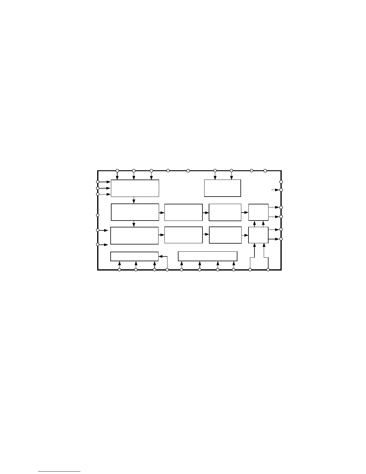
The I2S-bus data format being the digital output signal, goes
from the DASP on the CDR main board via flex and connector
J601 to the I/O board. Here it is presented to the D/A converter
AK4393. The DAC's analog outputs pass an amplification and filtering
circuit (opamp Q603, Q604). After the analog-out L and R signals are
sent to the headphone connector on the headphone board, analog out
UNBALANCE connectors on the AUDIO board. The DAC uses the
CL11-clock (11.2896 MHz), coming from the DASP on the CDR main
board.
DAC AK4393
Description
The AK4393 is a high performance, single-chip stereo, audio
DAC delivering 101dB dynamic range sample rate.
Block diagram
Figure 7-15
7.2.2 Analog-out path
DEM1
LRCK
BICK
SDAT
A
Audio Data
Interface
DEM0DVDD
CSN
AVD D
AOUTR+
8x
Interpolator
SCF
∆Σ
Modulator
AOUTR-
SCF
De-emphasis
Soft Mute
Control Register Clock Divider
De-emphasis
Control
PDN
CCLK
CDTI
P/S
MCLK CKS0
CKS1 CKS2 VREFH VREFL
AOUTL+
AOUTL-
VCOM
BVSS
AVSSDVSS
DIF2DIF1DIF0
SMUTE
De-emphasis
Soft Mute
8x
Interpolator
∆Σ
Modulator
DFS

Other manuals for Marantz CDR631

Questions and Answers:

Question and Answer IconNeed help?

Do you have a question about the Marantz CDR631 and is the answer not in the manual?

Marantz CDR631 Specifications

General IconGeneral
BrandMarantz
ModelCDR631
CategoryRecording Equipment
LanguageEnglish

Related product manuals