2-19
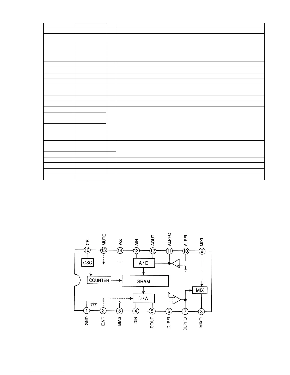
BU9253 (Digital delay)
Pin No. Port Name I/O FUNCTION
67 AVRTM I ECC interruption request input (end of output stream of 2060 bytes data) .
68,69 DGND Ð Ground for digital section.
70 SDA(I2C) I/O Serial data in/out from/to EEP-ROM & video encoder.
71 SCL O Serial clock output to the EEP-ROM & video encoder.
72 STAT I CD-DSP status input.
73 X0A I Not used.
74 X1A O Not used.
75 XSRTM I ECC interruption request input (end of block signal).
76 XINT.DEC I Interruption request from the Ziva MI-COM.
77 XINT.SER I Interruption request from the servo MI-COM.
78 OPEN-SW I Disc tray open detect input pin.
79 CLOSE-SW I Disc tray close detect input pin.
80 CLAMP-SW I Disc changer tray position detect input pin.
81 PHOT-IN I Disc changer tray position detect photo sensor input pin.
82 LOAD.F
O Loading motor direction control output.
83 LOAD.R
84 CHG.M.R
O Disc changer motor control output.
85 CHG.M.L
86 HSTX I hardware standby pin. (Pulled up)
87-89 MD0-MD2 I Bus mode setting pins.
90 RSTOUT I Reset signal input from the output control MI-COM.
92 X0 I
4 MHz crystal connecting pin.
93 X1 O
95-102 HAD00-HAD07 I/O System bus serial data/address I/O pins.
103-116 HA08-HA21 O System bus address output pins.
117,118 HA22,HA23 O System bus address output pins for chip select circuit.
120 ALE O System bus address latch enable output.