ut
Selector
Clock
Recovery
Clock
Generator
DAIF
Decoder
AC-3/MPEG
Detect
DEM
Audio
I/F
X'tal
Oscillator
PDN
INT0 P/S=”H”
LRCK
BICK
SDTO
DAUX
XTOXTI
RAVDDAVSS
CM1
CM0
OCKS1
OCKS0
DVDD
DVSS
TVDD
IPS1
RX0
RX1
RX2
RX3
IPS0
DIF0
DIF1
DIF2
DIT
TX0
Error &
Detect
STATUS
INT1
TX1
B,C,U,VOUT
4 to 2
VIN
MCKO2
MCKO1
Parallel Control Mode
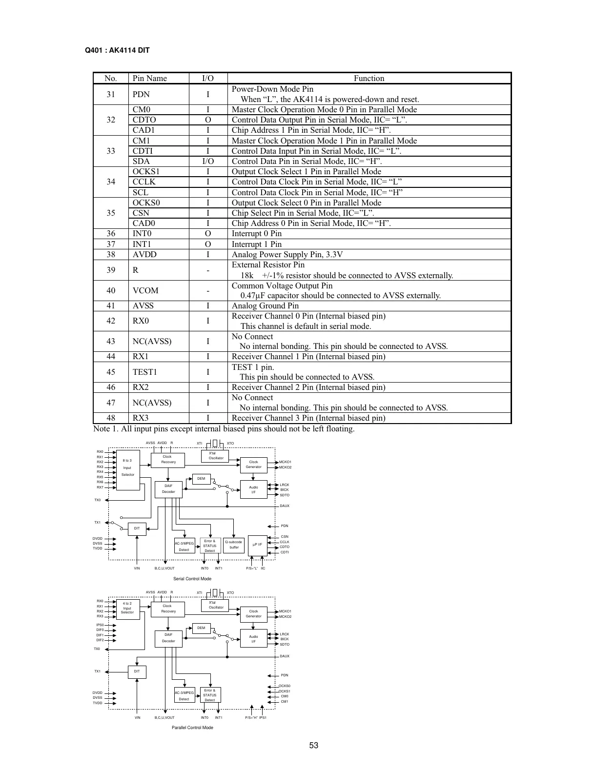
No. Pin Name I/O Function
31 PDN I
Power-Down Mode Pin
When “L”, the AK4114 is powered-down and reset.
CM0 I Master Clock Operation Mode 0 Pin in Parallel Mode
CDTO O Control Data Output Pin in Serial Mode, IIC= “L”.32
CAD1 I Chip Address 1 Pin in Serial Mode, IIC= “H”.
CM1 I Master Clock Operation Mode 1 Pin in Parallel Mode
CDTI I Control Data Input Pin in Serial Mode, IIC= “L”.33
SDA I/O Control Data Pin in Serial Mode, IIC= “H”.
OCKS1 I Output Clock Select 1 Pin in Parallel Mode
CCLK I Control Data Clock Pin in Serial Mode, IIC= “L”34
SCL I Control Data Clock Pin in Serial Mode, IIC= “H”
OCKS0 I Output Clock Select 0 Pin in Parallel Mode
CSN I Chip Select Pin in Serial Mode, IIC=”L”.35
CAD0 I Chip Address 0 Pin in Serial Mode, IIC= “H”.
36 INT0 O Interrupt 0 Pin
37 INT1 O Interrupt 1 Pin
38 AVDD I Analog Power Supply Pin, 3.3V
39 R -
External Resistor Pin
18k +/-1% resistor should be connected to AVSS externally.
40 VCOM -
Common Voltage Output Pin
0.47µF capacitor should be connected to AVSS externally.
41 AVSS I Analog Ground Pin
42 RX0 I
Receiver Channel 0 Pin (Internal biased pin)
This channel is default in serial mode.
43 NC(AVSS) I
No Connect
No internal bonding. This pin should be connected to AVSS.
44 RX1 I Receiver Channel 1 Pin (Internal biased pin)
45 TEST1 I
TEST 1 pin.
This pin should be connected to AVSS.
46 RX2 I Receiver Channel 2 Pin (Internal biased pin)
47 NC(AVSS) I
No Connect
No internal bonding. This pin should be connected to AVSS.
48 RX3 I Receiver Channel 3 Pin (Internal biased pin)
Note 1. All input pins except internal biased pins should not be left floating.
Q401 : AK4114 DIT