EasyManua.ls Logo

Marantz SD4050 /N1B User Manual

Marantz SD4050 /N1B
20 pages
To Next Page IconTo Next Page
Page #1 background imageLoading...
Page #1 background image
Service
Manual
Please use this service manual with referring to the user guide (D.F.U) without fail.
286W855010 AO
3120 785 22012
First Issue:1999.08
SD4050 /N1B, /U1B, /F1B
Cassette Deck
- SD4050 -
TABLE OF CONTENTS
1. TECHNICAL SPECIFICATION ...............................................................................1
2. BLOCK DIAGRAM ..................................................................................................2
3. WIRING DIAGRAM .................................................................................................3
4. ADJUSTMENT PROCEDURE ................................................................................5
5. SCHEMATIC DIAGRAM AND PARTS LOCATION ...............................................10
6. MICROPROCESSOR AND IC DATA ....................................................................17
7. EXPLODED VIEW AND PARTS LIST...................................................................19
8. ELECTRICAL PARTS LIST...................................................................................22
Printed in Japan
SD4050
Question and Answer IconNeed help?

Do you have a question about the Marantz SD4050 /N1B and is the answer not in the manual?

Marantz SD4050 /N1B Specifications

General IconGeneral
TypeCassette Deck
Track System4-track, 2-channel stereo
Heads3 (record, playback, erase)
MotorDC Servo Motor
Tape Speed4.76 cm/s
InputLine In
OutputLine Out
Tape TypeType I (Normal), Type IV (Metal)
Noise ReductionDolby B
Frequency Response20 Hz - 20 kHz

Summary

1. Technical Specification

2. Block Diagram

3. Wiring Diagram

4. Adjustment Procedure

4-1 Mechanical Adjustment

Details procedures for mechanical adjustments including wow, flutter, tape speed, and reel torque.

4-2 Electrical Adjustment

Covers electrical adjustments, safety precautions, and test locations for performance verification.

5. Schematic Diagram and Parts Location

6. Microprocessor and IC Data

Microprocessor Pin Functions

Details the input/output functions and port assignments for the microprocessor's pins.

Microprocessor Block Diagram

Illustrates the internal architecture and functional blocks of the microprocessor.

Microprocessor Pin Configuration

Shows the physical pin layout and connections for the microprocessor and associated ICs.
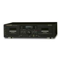
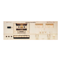
7. Exploded View and Parts List

8. Electrical Parts List

Related product manuals