Power amplifier
SM-17 / SM-17SA
314J855010 MIT
3120 785 22190
First Issue 1999.10
TABLE OF CONTENTS
SECTION PAGE
1. TECHNICAL SPECIFICATIONS ................................................................................................................. 1
2. BLOCK DIAGRAM ....................................................................................................................................... 2
3. TEST EQUIPMENT REQUIRED FOR SERVICING .................................................................................... 2
4. SCHEMATIC DIAGRAM .............................................................................................................................. 3
5. PARTS LOCATION (Pattern Side) .............................................................................................................. 5
6. EXPLODED VIEW AND PARTS LIST ......................................................................................................... 7
7. IDLING CURRENT ADJUSTMENT ........................................................................................................... 10
8. ELECTRICAL PARTS LIST ....................................................................................................................... 11
Service
Manual
SM17 /F1N, /N1G, /S1G
/N1B, /U1B
R
SM-17 / SM-17SA
Please use this service manual with referring to the user guide ( D.F.U. ) without fail.
TEMP
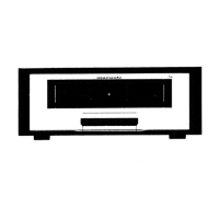
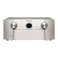
POWER AMPLIFIER SM-17SA
POWER
TEMP
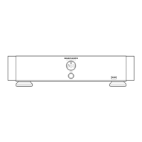
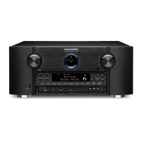
POWER AMPLIFIER SM-17
POWER
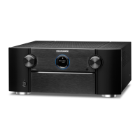
TEMP
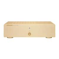
POWER AMPLIFIER SM-17SA
POWER
/F
/N
/S
/U