Do you have a question about the Marantz 7C Stereo Console and is the answer not in the manual?
Explains the manual's purpose for authorized warranty stations and service data for the Marantz Model 7C.
Information is intended for knowledgeable technicians; includes functional description and parts list.
Figure 1 shows the Model 7C's functional elements, signal flow, and dual channel design.
Details SR7's role in routing input, feedback, and output signals for various sources.
Describes preamp stages, gain levels, and selectable equalization networks for input sources.
Discusses specific EQ settings (78, RIAA, COL LP) and gain for PHONO positions.
Details the SELECTOR's input, feedback, and output sections shown in the block diagram.
Describes the function of the Tone Amplifier (V5) and associated filters.
Outlines the power supply design, including rectifiers and DC heaters.
Explains the adjustment of potentiometer R13 for preamp gain and frequency response.
Describes the TAPE switch function and signal routing to TAPE OUT.
Presents Figure 2 showing gain vs. frequency for various equalization settings.
Explains the MODE switch (SR7) for inter-channel selection (A, B, MONO, STEREO).
Describes the function and operation of the BALANCE and VOLUME dual potentiometers.
Details the Tone Amplifier (V5) and the effect of BASS and TREBLE controls.
Presents Figure 3 showing frequency response for tone controls.
Describes the function of low-frequency RC filters and high-frequency LC filters.
Presents Figure 4 showing frequency response for low and high-frequency filters.
Explains the power supply's rectifiers, capacity input filters, and DC heaters.
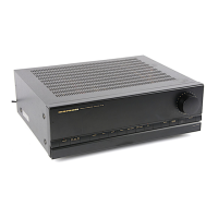
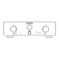
Identifies key components (tubes, selectors, controls) visible from the top of the unit.
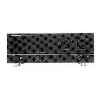
Identifies key components (rectifiers, potentiometers, ground post) visible from the bottom.
Lists DC voltages for each pin of tubes V1-V6 under specified conditions.
Notes on measurement methods, input voltage, signal status, and reference points.
Lists resistance values (ohms) for each pin of tubes V1-V6.
Notes on measurement units, tolerance, and reference points for resistance checks.
Presents the full schematic diagram illustrating all circuit interconnections and components.
Clarifies symbols and abbreviations used in the schematic, especially for capacitors.
Lists capacitors by reference designator, part number, and description.
Lists resistors by reference designator, part number, and description.
Defines abbreviations for component types like Ceramic, Electrolytic, and Carbon Composition.
Lists switches, tubes, fuses, knobs, and other components with part numbers.
Defines abbreviations for component types like Carb Comp and Dep Carb.