n. Remount exhaust screen band.
o. To reassemble the armature, pull main rotor leads
through the holes in the exciter rotor.
DO NOT PINCH ROTOR LEADS.
p. Replace the mounting bolt, lock washer, and
Belleville washer. Using a 9/16” socket on a torque
wrench, torque the mounting bolt to 30 to 35 ft-lb.
q. Reconnect main rotor leads to proper connections.
r. Reconnect all incoming power leads as shown on
wiring diagram.
s. Replace pot cover or control box cover.
t. Remove jack support from under engine flywheel
housing.
u. See preceding paragraph “a.” If necessary,
reconnect positive (+) lead to the engine cranking
battery.
ELECTRICAL CONNECTIONS
NOTE: INSURE THAT ALL ELECTRICAL CONNECTIONS ARE CORRECT BEFORE STARTING GENERATOR.
REFER TO THE AUTOMATIC VOLTAGE REGULATOR (AVR) MANUAL FOR SPECIFIC INSTRUCTIONS FOR
CONNECTING THE AVR.
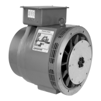
Dedicated 4 lead single phase generator connections.
SINGLE PHASE CONNECTION - DUAL VOLTAGE SERIES
VOLTAGE
L-L L-N
60 HZ 240 120
50 HZ 220 110
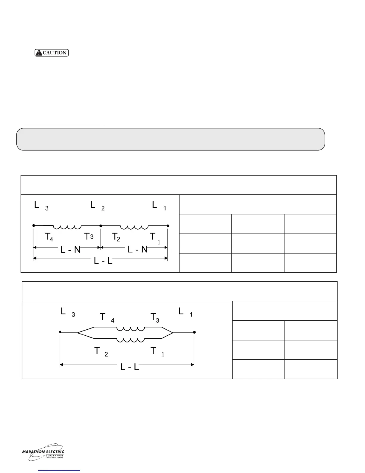
SINGLE PHASE CONNECTION - SINGLE VOLTAGE PARALLEL
VOLTAGE
L-L
60 HZ 120
50 HZ 110
4
 Loading...