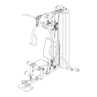
STEP 6 (See Diagram 6 & Upper Cable Loop Diagram)
A.) Attach the 163” Upper Cable (#33) to the opening on the front of Upper Frame (#1).
Make sure the ball stopper is underneath the Frame. Attach a Pulley (#47) to the
Cable.
B.) Secure the Pulley to the opening with one M10 x 3 ½” Allen Bolt (#77), two Pulley
Bushings (#49), and one M10 Aircraft Nut (#91).
C.) Draw the Cable over the Pulley along the Upper Frame towards the back of the
machine to the opening in the middle of Upper Frame. Repeat Procedure B above to
install a Pulley.
D.) Draw the Cable around the Pulley then back to the upper opening on the Front Press
Base (#2). Attach a Pulley to the opening. Secure it with one M10 x 6 ¼” Allen Bolt
(#79), two ∅ ¾” Washers (#92), and one M10 Aircraft Nut (#91).
E.) Draw the Cable around the Pulley then towards the upper opening on the Vertical
Frame (#4). Repeat Procedure B above to install a Pulley.
F.) Draw the Cable around the Pulley and back to the lower opening on the Front Press
Base. Repeat Procedure D above to install a Pulley.
G.) Draw the Cable around the Pulley then to the lower opening on the Vertical Frame.
Repeat Procedure B above to install a Pulley.
H.) Draw the Cable underneath the Pulley then pull upward to another opening on the back
of the Upper Frame. Repeat Procedure B above to install a Pulley.
I.) Draw the Cable around the Pulley then downward. Attach a Pulley to the top hole on
the Double Floating Pulley Brackets (#22).
J.) Secure the Pulley to the brackets with one M10 x 2” Allen Bolt (#93), two Pulley Covers
(#94), two Ø ¾” Washers (#92), and one M10 Aircraft Nut (#91). Let the Bracket
hanging for now.
K.) Draw the Cable around the Pulley then upward to the open bracket between the two
Guide Rods. Repeat Procedure J above to install a Pulley.
L.) Draw the Cable around the Pulley then downward to the Selector Rod (#28). Securely
thread the Head Bolt at end of the Cable into the Selector Rod.
15