Do you have a question about the MarelliGenerators M40FA640A/A MARK I and is the answer not in the manual?
Provides essential safety warnings regarding lethal voltages and high temperatures.
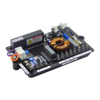
Describes the suitability of the voltage regulator for Marelli Motori generators.
Specifies the accuracy of voltage regulation under steady state conditions.
Lists supply voltage, power supply, dissipated power, and voltage sensing.
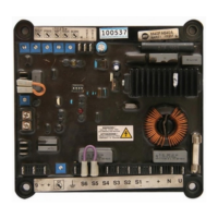
Identifies terminals 'U', 'N' for power supply connection.
Details terminals for three-phase or single-phase voltage sensing.
Specifies output terminals '+', '-' for DC voltage output.
Explains connection and function of external potentiometers for voltage regulation.
Describes the function and setting of the underfrequency limiter.
Explains the use of analogue input for exciter field control.
Provides a step-by-step procedure for setting the over-excitation limiter.
Adjusts generator output voltage using internal or external potentiometers.
Sets the frequency threshold for low speed protection.
Sets the excitation voltage threshold for the over-excitation limiter.
Adjusts regulator stability and response time.
Affect transient response; ON makes it faster.
Used for quick setting of excitation limiter; OFF disables time delay.
Controls low speed protection with V/f slope adjustment.
| Thermal Drift | 0.02%/°C |
|---|---|
| Input Frequency | 50/60 Hz |
| Output Voltage | Max 90 Vdc @ 207 Vac input |
| Frequency | 50/60 Hz |
| Voltage Regulation Accuracy | ±1% |
| Storage Temperature | -40 to +85 °C |