EasyManua.ls Logo

MarelliGenerators M40FA610A - User Manual

MarelliGenerators M40FA610A
11 pages
Print Icon
To Next Page IconTo Next Page
Loading...
M40FA610A - M40FA610A/A
Manuale dell’Utente - User Manual
Regolatore di Tensione per Generatori Sincroni Trifase
A
u
tomatic Voltage Regulator for Three-phase Synchronous Generators
(Issued: 03.2011)
SIN.NT.010.7
CALL US TODAY
1-888-POWER-58
REQUEST A QUOTE
parts@genpowerusa.com
SHOP ONLINE
www.genpowerusa.com
CALL US TODAY
1-888-POWER-58
REQUEST A QUOTE
parts@genpowerusa.com
SHOP ONLINE
www.genpowerusa.com
Email: parts@genpowerusa.com
Question and Answer IconNeed help?

Do you have a question about the MarelliGenerators M40FA610A and is the answer not in the manual?

Summary

Safety Precautions

Electrical and Thermal Hazards

Warns about lethal voltage on energized components and high temperatures.

Installation and Wiring Safety

Emphasizes using qualified personnel and performing operations with the generator stopped.

Calibration and Testing Safety

Details safe practices for calibration with running generator, using insulated tools.

Application Overview

Technical Specifications

Terminal Connections

Power Supply and Sensing Terminals

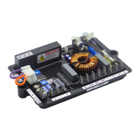
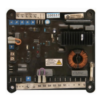
Details terminals for power input and generator voltage/current sensing.

Output and Auxiliary Connections

Terminals for exciter field, Varicomp, and external control devices.

Frequency Selection and Grounding

Terminals for 60Hz mode selection and grounding connections.

External Potentiometer Usage

Potentiometer Adjustments

Voltage (VOLT) Potentiometer

Adjusts the generator output voltage setpoint.

Frequency (FREQ) Potentiometer

Sets the low-speed protection corner frequency.

Stability (STAB) Potentiometer

Controls regulation stability and response time.

Droop Adjustment

Low Speed Protection

Stability Setting

Droop Kit Device

Microswitch Functions

Micro-switch 1 & 2 (Response Time)

Adjusts the transient response time of the regulator.

Micro-switch 3 (Low Speed Protection)

Configures standard or proportional low speed protection.

Micro-switch 4 & 5 (Disabled)

Indicates that micro-switches 4 and 5 are not enabled.

Fuse and EMI Suppressor

Wiring Diagram: 6 Terminals + Varicomp

Wiring Diagram: 12 Terminals + Varicomp

Wiring Diagram: 6 Terminals + Aux. Winding

MarelliGenerators M40FA610A Specifications

General IconGeneral
BrandMarelliGenerators
ModelM40FA610A
CategoryController
LanguageEnglish

Related product manuals