(CR0500390) 4/9
Replacement of burner injector and adjustment of
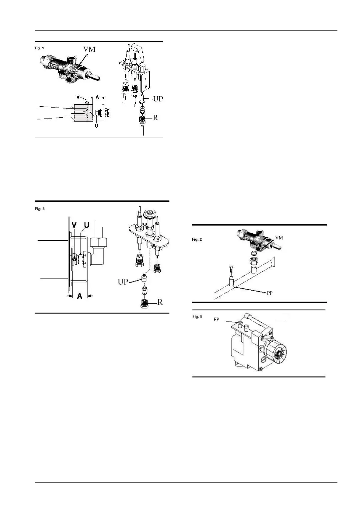
burner air flow of oven (Fig. 3)
• Remove the panel under oven's door.
• Unscrew the existing injector "U" and replace with the one
indicated in Table T1 in Appendix.
• Position the air regulator at the distance “A” indicated in
Table T2 in Appendix.
• Retighten screw V and seal it with red paint.
Adjustment of minimum flow to the cooking hob burners
(Fig. 1)
• Remove the front panel.
• Unscrew the existing screw "VM" and replace it with the
one indicated in Table T1 in Appendix.
Replacement of pilot burner injector of cooking hob and
oven (Fig. 1-3)
• Remove pan grids, burner units, trays, front panel.
• Remove the panel under the oven's door.
• Unscrew fitting R and replace injector UP with the one
indicated in Table T1 in Appendix.
• Retighten fitting R.
Adjustment of the gas control outlet pressure
• The outlet pressure adjustment screw is factory
commissioned (1 turn closed from fully open) and sealed
with red paint.
No adjustment are required in case of conversion to a
different type of gas.
COMMISSIONING PROCEDURE
Testing the gas system
• Switch on the appliance following the instructions for use.
Test burners ignition and flame uniformity. Also check the
appliance for gas leaks and make sure the gas exhaust system
functions correctly.
• If necessary, consult the “Troubleshooting guide” below.
Testing the gas nominal thermal power
• After installation, conversion to a different type of gas or
servicing, check the nominal thermal power of the appliance.
• The appliance functions at the nominal thermal power when
is fitted with the appropriate injectors for the gas used, the
gas control is commissioned according to manufacturer
requirements (see paragraph "Adjustment of the gas control
outlet pressure), and the gas pressure measured at the
manifold pressure test point is commissioned to the
appropriate nominal value as specified in Table T5 in
Appendix.
Setting the manifold gas pressure (Fig. 2)- (Fig. 5 only
for ABF7-8G)
• Remove the front panel.
• Remove sealed bolt PP from the test point pressure and
connect the pressure gauge pipe.
• Switch on the appliance following the instructions for use
and commission the test point pressure values to the
appropriate nominal values as specified in Table T5 in
Appendix.
Testing the electric oven
• Switch on the oven following the instructions for use.
• Check the correct functioning of the controls and heating
elements, trying the various combinations (bottom heating,
top heating and simultaneous top and bottom heating).
• If necessary, consult the “Troubleshooting guide” below.
Cheking the electrical nominal thermal power
• After installation, check the nominal thermal power of the
appliance.
• The appliance functions at the nominal thermal power when
the electrical power supply is as indicated in Table T1 in
Appendix.
TROUBLESHOOTING GUIDE
 Loading...