(CR0500390) 3/9
INSTALLATION INSTRUCTIONS
CONFORMITY TO REGULATIONS AND LAWS
The appliance is to be installed by an authorised person in
accordance with AS5601 - the installer must ensure the
installation complies with all regulatory and manufacturer
requirements and operationally and functionally test, make
necessary adjustments and commission the appliance as part
of installation.
WARNING
The manufacture declines any responsibility if these
obligations are not respected.
INSTALLATION
The overall dimensions/connections and technical data are
given in the appendix.
If the appliance cannot be adjusted to perform correctly call
the tecnichal assistant service.
Positioning
• Install the appliance in a suitably ventilated environment.
• Position the appliance at least 10 cm from surrounding
walls. This distance may be reduced if the walls are
flameproof or protected by insulating material.
• This appliance is not designed for built-in installation.
• Remove the protective film from the external panels.
Use a suitable solvent to remove any glue residue.
• In stand-alone installations, appliances 40 or 60 cm wide
must be fixed to the floor using the flanged feet.
• Level the appliance by means of the adjustable feet.
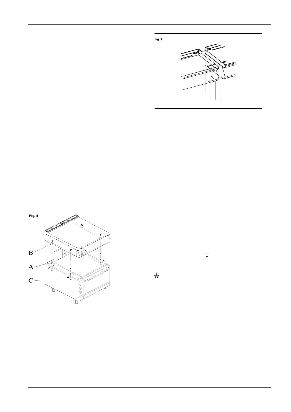
Joining top on oven base (Fig.5)
•
Screw the bolts (A) provided into the base (C).
•
Position the top so that bolts A fit with the corresponding
seats (B) in the top.
Joining appliances togheter in line (Fig. 4)
• Position the appliances next to each other and level to the
same height.
• Fix the appliances together using the holes provided in the
side of the top
Connecting to the gas supply
• Install a shut-off valve upstream of the appliance, in a
place easily accessible.
• Check if the appliance is adjusted for the type of gas with
which it will be supplied. If not, convert it according to the
instructions in the paragraph "Conversion to different type of
gas".
• Check that there are no leaks at the connection points.
Connecting to the electrical power supply
• The appliance is set to operate at the voltage indicated on
the data plate.Total power is given in table T6 in Appendix.
• The appliance must be supplied with a separate electrical
line using a flexible rubber cable with insulating properties
not inferior to H07RN-F. The length of the cable between the
cable clamp and the connection terminal blocks must be such
that the live conductors tighten before the yellow/green earth
wire, in case the cable come out of the cable clamp.
• Install suitable automatic cut-off switches (contact opening
of at least 3 mm) and highly sensitive automatic differential
protection devices. These must guarantee protection against
direct or indirect contact with live parts and against currents
towards earth in the event of malfunction (maximum
dispersion current 1 mA/kW).
Earth and equipotential connection
• The appliance must be earth connected on the terminal
block marked by the symbol
located beside the input line
terminal block.
• The metal structure of all the appliances installed must be
connected together on the terminal marked by the symbol
located close to the earth terminal (equipotential system).
CONVERSION TO A DIFFERENT TYPE OF GAS
To convert the appliance to a different gas supply, follow the
instructions below.
Use the injectors contained in the bag supplied with the
appliance.
Replacement of burner injector and adjustment of
burner air flow of cooking hob (Fig. 1)
• Remove pan grids, burner units, trays, front panel.
• Unscrew the existing injector "U" and replace it with the
one indicated in Table T1 in Appendix.
• Position the air regulator at the distance “A” indicated in
Table T2 in Appendix.
• Retighten screw V and seal it with red paint.
 Loading...