Series 5 Digital Force Gauges User’s Guide
10
5.6 External Trigger (ET)
This mode of operation is useful for measuring electrical contact activation force as well as
synchronization of multiple instruments for a “snapshot” view of applied forces. It is possible to capture
the reading with a normally open contact (high to low transition of the trigger signal) or a normally closed
contact (low to high transition).
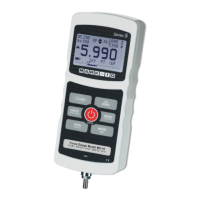
Before the parameters of External Trigger Mode can be configured, it must be enabled. To do so, enter
the main menu, select External Trigger, scroll to one of the four available options and press ENTER.
The options are as follows:
Option Description
Momentary High Low The display will freeze the captured reading until ZERO is pressed. Applies
to a high to low transition of the trigger signal.
Momentary Low High The display will freeze the captured reading until ZERO is pressed. Applies
to a low to high transition of the trigger signal.
Maintained High The display will show the captured reading only for as long as a high signal
is maintained.
Maintained Low The display will show the captured reading only for as long as a low signal
is maintained.
After the selection has been made and the menu has been exited, press MODE until ET is displayed.
External Trigger mode is now armed. Refer to the pin diagram in the Communications and Outputs
section for connection information.
To exit External Trigger mode, press MODE and select the desired measuring mode.
Note: As long as external trigger has been enabled, it is still active even if the gauge is in Real Time
mode. After the display freezes, any programmed set points will be active. However, if the gauge is in
External Trigger mode, any programmed set points will be inactive.
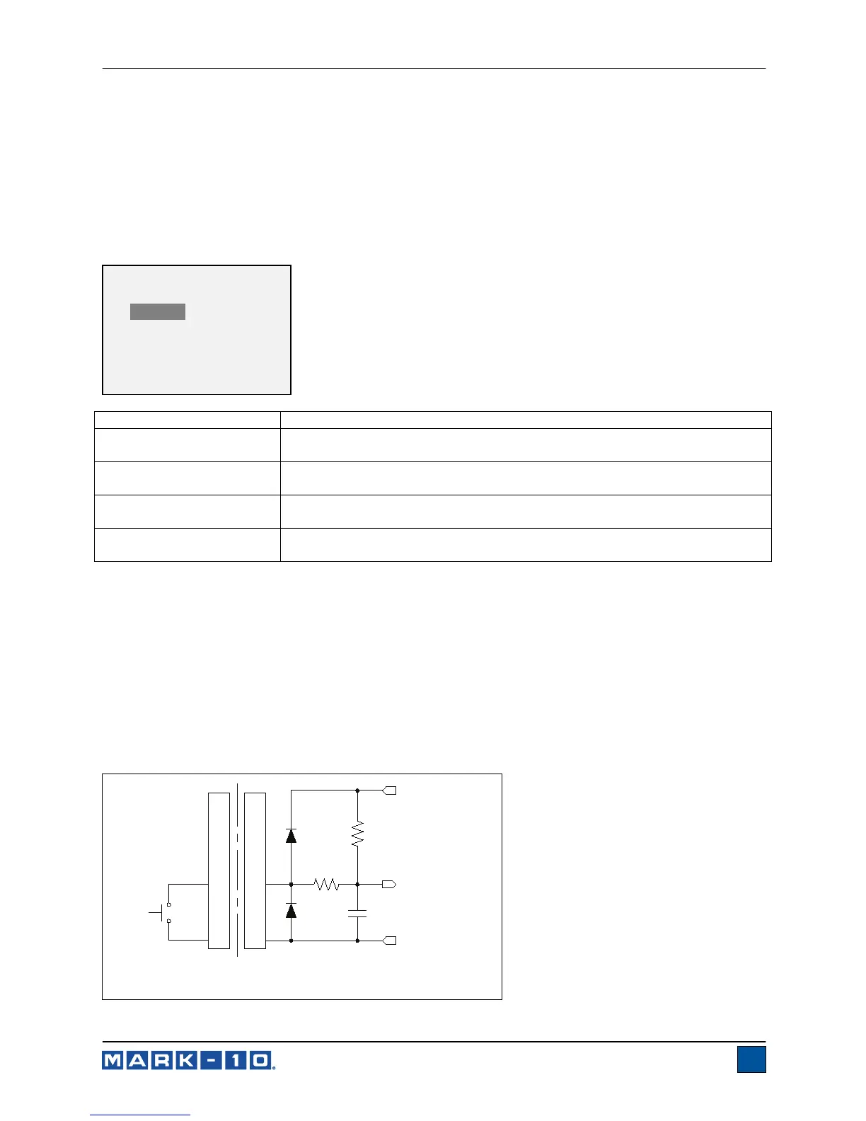
5.6.1 External Trigger Schematic Diagram
14
GND
1
IN
22k
SWITCH UNDER TEST
GAUGE
+3.3V
TO MICROPROCESSOR
0.1 uF
GND
BAT54SLT1G
330 Ohm
(NO OR NC)
USER - SUPPLIED
EXTERNAL TRIGGER
* Disabled
Momentary Hi->Lo
Momentary Lo->Hi
Maintained High
Maintained Low
 Loading...