Series 5 Digital Force Gauges User’s Guide
6
and on.
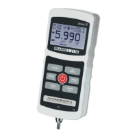
4 Primary reading /
Kinetic COF
The current displayed force reading. See Operating Modes section for
details. For the M5-2-COF gauge, this reading represents the kinetic
coefficient of friction when the gauge is set to COF unit of measurement (see
Units indicator below) and has completed an Average sequence (see
Operating Modes section for details).
5 Load bar
Analog indicator to help identify when an overload condition is imminent. The
bar increases either to the right or to the left from the midpoint of the graph.
Increasing to the right indicates compression load, increasing to the left
indicates tension load. If set points are enabled, triangular markers are
displayed for visual convenience. This indicator reflects the actual load, which
may not correspond to the primary reading (depends on operating mode).
The ZERO key does not reset the load bar. See Operating Modes section for
details.
6 Units
The current measurement unit. Abbreviations are as follows:
lbF – Pound-force
ozF – Ounce-force
kgF – Kilogram-force
gF – Gram-force
N – Newton
kN – Kilonewton
mN – Millinewton
COF – Coefficient of friction (M5-2-COF gauge only)
Note: not all gauge capacities measure in all the above units. Refer to the
capacity / resolution table in the Specifications section for details.
7 Mode
The current measurement mode. Abbreviations are as follows:
RT – Real Time
PC – Peak Compression
PT – Peak Tension (static COF for M5-2-COF gauge)
A – Average Mode (kinetic COF for M5-2-COF gauge)
ET – External Trigger Mode
See Operating Modes section for details about each of these modes
8 Number of stored
data points
The number of stored data points in memory, up to 1000. Displayed only if
Memory Storage is enabled for the DATA key.
9 Battery / AC
adapter indicator
Either the AC adapter icon or battery power icon will be shown, depending on
power conditions. Refer to the Power section for details.
10 Automatic data
output indicator
If Auto Output has been enabled under Serial / USB Settings, this indicator
is displayed. When automatic data output is occurring, the icon becomes
animated. See Communications and Outputs section for details.
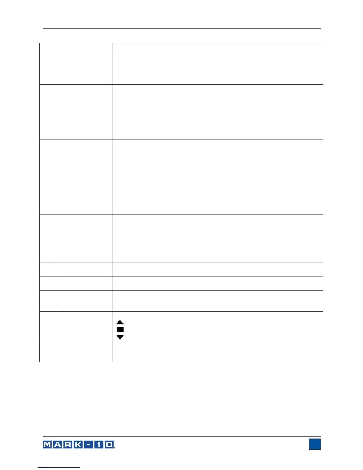
11 High / low limit
indicators
Correspond to the programmed set points. Indicator definitions are as follows:
– the displayed value is greater than the upper force limit
– the displayed value is between the limits
– the displayed value is less than the lower force limit
12 Set points
The programmed force limits. Typically used for pass/fail type testing. 1, 2, or
no indicators may be present, depending on the configuration shown in the
Set Points menu item.
 Loading...