Modifications to the compressor cubicle:
Step Action
1 Adjust the motor overload (FM1) setting.
2 Control transformer (T1) – Move the primary connection from 230V to the desired voltage.
3 Replace the control fuses (F1) 10.3 x 38mm with the ones provided (see further).
Use 1A fuses for 460V or 2A for 208V
4 Modify the motor terminal bridge configuration in the cubicle (X2). See further for details.
5 Replace the voltage sticker by the appropriate voltage sticker provided.
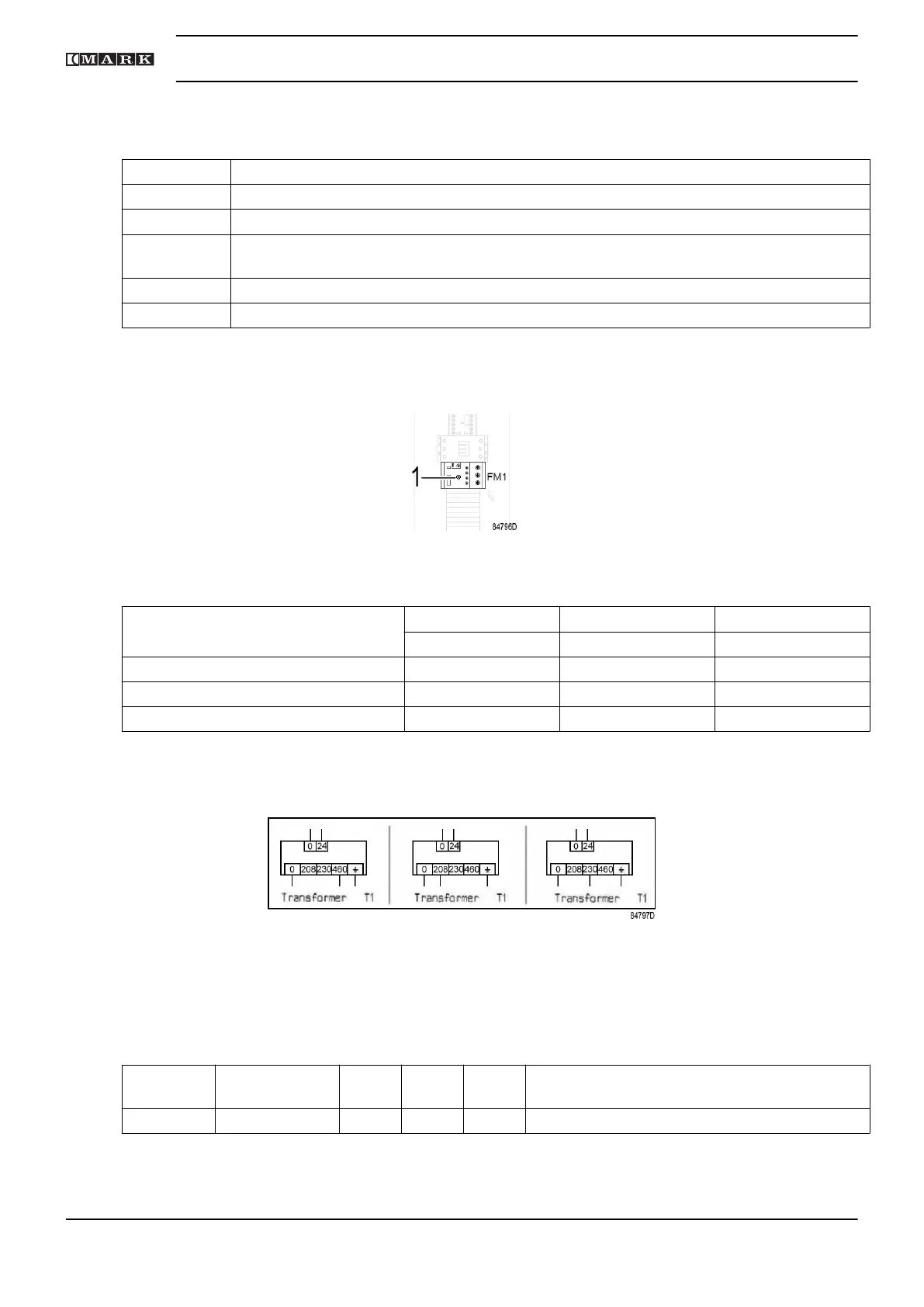
Motor overload relay (FM1) setting:
Rotate the adjustment screw (1) on the front of the relay to the required value.
Adjustment screw of the motor overload
Motor overload (FM1) settings 7.5 kW 11 kW 15 kW
10 hp 15 hp 20 hp
208 V 36.3 48 33.2
230 V (Standard factory setting) 34.3 45 30
460 V 16.9 22.5 15
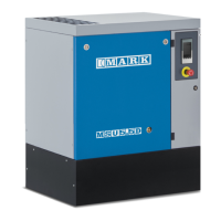
Control transformer (T1):
Move the wire to the terminal marked with the desired voltage (208 V, 230 V or 460 V).
Transformer T1
Fuses F1 – F3:
The fuses are supplied with the compressor.
Fuses Fuse rating
(V)
208 V 230 V 460 V Class
F1 600 V AC 2 A 2 A 1 A UL class JDYX or JDYX2 10.3 x 38mm
Motor terminal bridge configuration:
Instruction book
50 2920 7201 40