4
Note: The conversion must be done by an authorized techni-
cian (example: Märklin digital dealer). Conversion work done
by anyone else will void the manufacturer‘s warranty.
WARNING! This product contains magnets. Swallowing more than one
magnet may cause death in certain circumstances. If necessary, see a
doctor immediately.
Preparation
• Check to make sure that the locomotive is in proper
mechanical condition.
• Check to make sure that this conversion set is the right
one for the locomotive and the type of motor.
• Check electrical load on the decoder.
Assigning Auxiliary Functions to the Decoder
Maximum load at the motor output 800 milliamps
Maximum load at the function output 150 milliamps
Maximum total, short term load 1100 milliamps
A maximum of 2 no. 610 080 light bulbs or 1 no. 610 040 light bulb
per function output
Installing the Motor
1. Step: Remove the brush plate, armature, eld, and
electronic circuit or reverse unit.
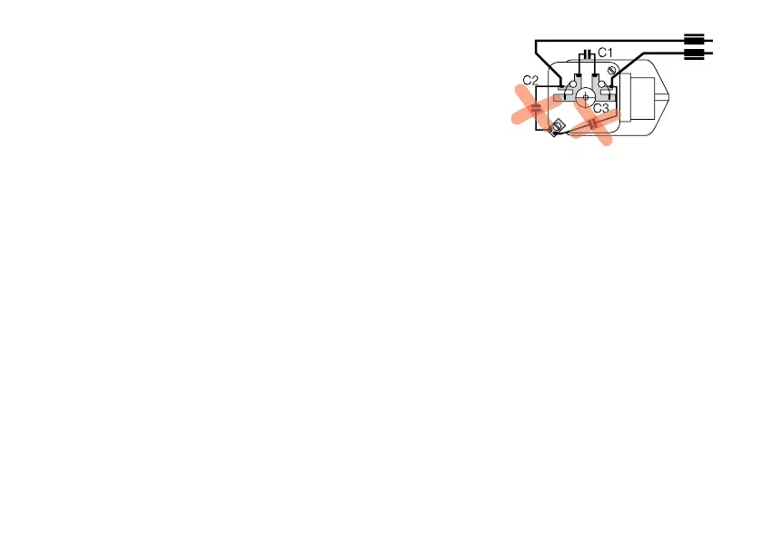
2. Step: Remove the condensers C2 and C3 from the
brush plate.
3. Step: Check the gear drive and renew if necessary.
4. Step:
Install the new eld, armature, and brush plate.
Wiring
Note: The con-
densers C2 and C3
must be removed!
The motor must not
have any ground
connection (to the
locomotive frame)
by means of radio / television interference suppression
components!
1. Connect the red and brown power wires (track).
2. Connect the headlights (gray wire at the front, yellow
wire at the rear). Connect the ground wire (orange) only
if the headlights are not grounded through the locomotive
frame.
3. Connect the motor wires (green and blue). Do not forget
the chokes at the motor connections!
4. Change the green and blue wire connections if necessary
so that the locomotive‘s direction of travel agrees with the
headlights that are on for a given setting.
The orange wire must never be connected to the brown wire!
Examples of connections in Figures 1 and 2