Do you have a question about the marklin 24802 and is the answer not in the manual?
Crucial safety instructions for first-time use, including warnings about sharp edges and small parts.
Guidance on operating instructions, storage, and obtaining repairs or spare parts.
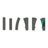
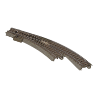
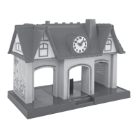
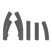
List of all items included in the package, such as track pieces and the operating instruction.
Details on the turnout decoder's technical data, including load capacities and voltage ratings.
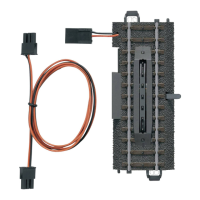
Instructions for safely connecting the power pack and setting up track components.
Decoder supports Märklin Motorola (MM) and Digital Command Control (DCC) protocols.
How to set the operating mode using DIP switches, referencing page 30 for details.
Information on setting addresses via DIP switches (MM/DCC) and CV programming (DCC).
Steps for programming the turnout decoder using the fx (MM) / Motorola system.
Details on DCC CV programming for address, configuration, and turnout lantern settings.
Method for setting and generating DCC addresses exceeding 255 using CV programming.
Using DIP switch position 10 to select between DCC and fx (MM) operating modes.
Guidance on setting addresses by activating specified DIP switches marked 'on'.
Table mapping turnout addresses to DIP switch settings for fx (MM) and DCC protocols.
Key explaining DIP switch numbering and function for setting addresses.
Continued table mapping turnout addresses to DIP switch settings for fx (MM) and DCC protocols.
Continued key explaining DIP switch numbering and function for address setting.
Continued table mapping turnout addresses to DIP switch settings for fx (MM) and DCC protocols.
Continued key explaining DIP switch numbering and function for address setting.
Continued table mapping turnout addresses to DIP switch settings for fx (MM) and DCC protocols.
Continued key explaining DIP switch numbering and function for address setting.
Continued table mapping turnout addresses to DIP switch settings for fx (MM) and DCC protocols.
Continued key explaining DIP switch numbering and function for address setting.
Continued table mapping turnout addresses to DIP switch settings for fx (MM) and DCC protocols.
Continued key explaining DIP switch numbering and function for address setting.
Continued table mapping turnout addresses to DIP switch settings for fx (MM) and DCC protocols.
Continued key explaining DIP switch numbering and function for address setting.
Continued table mapping turnout addresses to DIP switch settings for fx (MM) and DCC protocols.
Continued key explaining DIP switch numbering and function for address setting.
Continued table mapping turnout addresses to DIP switch settings for fx (MM) and DCC protocols.
Continued key explaining DIP switch numbering and function for address setting.
Continued table mapping turnout addresses to DIP switch settings for fx (MM) and DCC protocols.
Continued key explaining DIP switch numbering and function for address setting.
Continued table mapping turnout addresses to DIP switch settings for fx (MM) and DCC protocols.
Continued key explaining DIP switch numbering and function for address setting.
Addresses over 511 require DCC format and CV programming on the programming track.
Critical warning against removing the cover for the turnout linkage mechanism.
Warnings in multiple languages (FR, NL, ES) advising not to remove the mechanical cover.
Diagram illustrating the length grid and component dimensions, using a 360 mm base unit.
Notes on FCC compliance and required adjustments for operating the product in the USA.