8
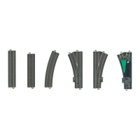
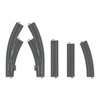
Taking track
apart
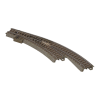
Turnout decoders are already built into the turnouts. These can
be operated digitally.
The addresses for the turnout decoders can be changed
with the DIP switches (see Page 31ff) or with programming
(see Page 9).
The last respective address setting is valid, regardless of
whether it was done with programming or with the DIP
switches.
The turnout decoders come from the factory programmed to
addresses 5 and 6 (the setting for the DIP switches can vary
from the actual programming).
The procedure for controlling the turnouts digitally can be found
in the operating instructions for your digital controller.
A selection of controllers can be found on Page 28. The turnout
decoder addresses can be changed if desired. See Page 30 to
do this.
Functions for the Turnout Decoder
• Capableofmulti-protocols:fx(MM)andDCC
• SettingthemodeofoperationbymeansofDIPswitches,
see Page 30
• AddressesthatcanbesetwithDIPswitches:
1-256
(MM) (6021 Control Unit / 60651/60652 Mobile Station)
1-320 (MM) (602xx Central Station / 60653/60657 Mobile
Station)
1-511 (DCC)
• ProgrammableaddressesusingCVs:1-2,044 (DCC)
• The last respective address setting is valid, regardless of
whether it was done with programming or with the DIP
switches
• ChangestocharacteristicscanbedonewithCVs
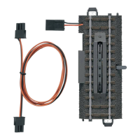
• Digitalsignal:transferindependentofthepowersupply
• Powersupplydoneusingthedigitalpowercircuit
• Alternativepowersupply
• Solderpadsforconnectionsforturnoutlanterns
• Turnoutlanternscanbeturnedonoroff