14
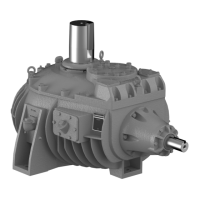
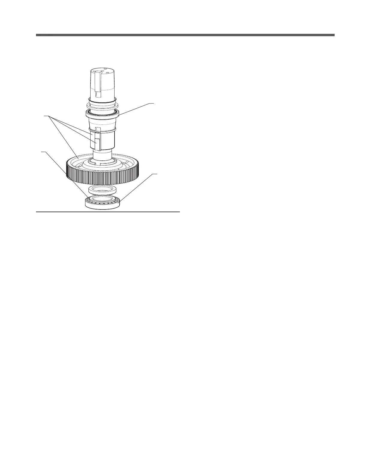
Figure 14 Fan Shaft Assembly
1
2
Fan Shaft Assembly
Part numbers and references—refer to Figures 6 and 14.
1. Install the key spacer ring. Install helical gear key and press
helical gear (201) on fan shaft.
2. Press lower bearing spacer (40) on fan shaft.
3. Press bottom bearing cone (421) onto fan shaft.
4. Press upper bearing cone (422) on fan shaft
5. Install lower fan shaft bearing cup (421) into Geareducer
case (not illustrated).
Final Assembly
Part numbers and references—refer to Figure 15.
1. Install O-ring (702) onto pinion cage subassembly.
2. Bolt pinion cage subassembly to case using proper number
of shims to give indicated pinion setting distance which is
etched on front face of pinion gear. See Figure 11. Tighten
to 75 ft·lb
ƒ
(102 N·m) torque.
3
4
3. Lower fan shaft and interstage shaft subassemblies into case
simultaneously. Engage marked spiral bevel ring gear teeth
with marked spiral bevel pinion tooth. The gear and pinion
are match-marked when lapped and must be assembled the
same way. The ring gear has the end of two teeth marked “X”
and the pinion has one tooth so marked— the gears should
be engaged with the X-marked pinion tooth between those
marked on the ring gear. Match mark location can be checked
through the inspection opening.
4. Apply a coat of Permatex
®
Form-a-Gasket No. 2 to surface of
Geareducer case which mates with case cover. Lower case
cover subassembly onto case, piloting both shaft subassem-
blies into their respective bores.
5. Install dowel pins (20) to align bearing bores. Fasten case cover
to case with cap screws and eye bolts tightening to 75 ft·lb
ƒ
(102 N·m) torque.
6. Position top interstage cap shims and install interstage bear-
ing cap with place bolts tightening to 85-90 ft·lb
ƒ
(116-122
N·m) torque.
7. Install upper fan shaft bearing cup (422) into Geareducer
case cover (not illustrated).
8. Adjust shims to give proper backlash—.007–.009" normal
(.178–.228mm)—between spiral bevel gears. See Gear Set-
ting Procedure, page 15.
9. Fan shaft bearing must be preloaded to .001–.003" (.025–
.076mm) in the following manner:
a. For cases that have the fan shaft lip seal, press the new
lip seal into the labyrinth ring. Install labyrinth ring in case-
cover initially with a quantity of shims between cover and
labyrinth ring to insure that axial bearing end play exists.
Tighten labyrinth ring cap screws to 35 ft·lb
ƒ
(48 N·m)
torque.
b. Mount a dial indicator to measure axial movement of fan
shaft. Support indicator stand on the cover or interstage
cap adjacent to fan shaft and position indicator to read
on machined top surface of fan shaft
c. Rotate the fan shaft slowly in one direction until all down-
ward movement stops. Rotation is necessary to align the
bearing rollers and seat roller ends on cone lip. Record
the dial indicator reading or zero the indicator.
d. Move shaft in the opposite axial direction by attaching to
the shaft with a swivel joint and hoist and lifting on shaft.
Lifting force should be 800 lb (363 kg) to sufficiently
overcome the weight of the fan shaft assembly. Rotate
the shaft slowly in one direction until all axial movement
stops. Record the dial indicator reading.
field repair
 Loading...