Do you have a question about the Mars COMFORT-AIRE CMA18SD-1 and is the answer not in the manual?
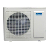
| Tonnage | 1.5 |
|---|---|
| BTU | 18000 |
| Cooling Capacity (BTU/h) | 18000 |
| Heating Capacity (BTU/h) | 18000 |
| Phase | 1 |
| Refrigerant | R410A |
| Voltage (V) | 208-230 |
Strict adherence to installation instructions, use of specified parts, and proper location are crucial.
Ensures proper grounding, avoids flammable gas areas, and mandates correct drainage piping.
Steps for setting thermostat, fan switch, and general operating tips for optimal cooling.
Wait at least 3 minutes after turning off before restarting to prevent damage.
Instructions for cleaning indoor air filters and outdoor unit coils for optimal performance.
Unauthorized alterations or parts void warranty and can create safety hazards.
Guidance on inspecting packages for damage upon arrival and filing claims.
Specifies the optimal outdoor temperature range for cooling and warranty implications.
Details compatibility with various indoor units and the importance of metering devices.
Highlights the need for fan time delay and proper thermostat selection/placement.
Mandates the use of an in-line filter drier, as it is not factory provided, to maintain warranty.
Guidance on selecting the optimal location and mounting the unit securely.
Ensuring proper airflow, protection from elements, and avoiding unit interference.
Specifies minimum clearances around the unit for air inlets, outlets, installation, and maintenance.
Recommendations for anchoring the unit, especially in high wind or earthquake-prone areas.
Details on adhering to NEC/local codes, providing branch circuits, and voltage consistency.
Procedure for removing the cover, connecting cables, forming loops, and insulating conductors.
Warning about potential malfunctions and the need for qualified electricians for all wiring.
Illustrations of terminal block connections for 12K and 18K-48K models.
Advises referring to thermostat instructions for additional wiring details.
Detailed circuit diagram for the 12K model, showing component connections.
Detailed circuit diagram for the 18K model, showing component connections.
Disclaimer stating that diagrams are for reference and actual wiring prevails.
Circuit diagrams for 24K and 30K models, illustrating electrical connections.
Detailed circuit diagram for the 36K model, showing component connections.
Note that diagrams are for reference only and actual wiring should be followed.
Detailed circuit diagram for the 48K model, illustrating electrical connections.
Note that diagrams are for reference only and actual wiring should be followed.
Discusses line length, bends, pressure drop, oil return, and tube sizing.
Guidance on tubing insulation, support, avoiding sags, noise transmission, and sharp edges.
Prohibits atmospheric discharge of refrigerant; service by qualified personnel only.
Unit comes with R-410a charge; additional charge needed for tubing.
Service valves are shipped closed; do not open until leak testing and evacuation are complete.
Step-by-step guide for pressure testing, evacuation to 500 microns, and checking for leaks.
Unit operation is automatic and depends on thermostat settings.
Ensure all panels are installed, power is on, and thermostat is connected before operation.
Steps for checking system components, fan operation, and initiating cooling.
System performance depends on proper charge; operating conditions affect pressures.
Details on charging for tubing, metering devices, TXVs, and critical charging.
Provides a formula and table for calculating additional refrigerant based on pipe length.
Perform a final visual check, complete details, and clean the installation area.
Demonstrate unit operation to the homeowner/user and explain its functions.
Utilize the pressure/temperature chart to verify system performance against conditions.
Warrants all parts against defects in workmanship and materials for one year.
Warrants the compressor for five years total, covering four additional years after the first year.
Specifies a one-year parts warranty for commercial, business, or rental applications.
Lists items not covered by the warranty, such as normal maintenance and labor charges.
Outlines requirements for warranty coverage, including proper operation and installation.
Explains warranty start date based on purchase receipt and the need for proof.
States the sole remedy is replacement of defective parts; labor is not covered.
Disclaims implied warranties and limits liability for consequential or incidental damages.
Instructions on how to contact for warranty claims and required documentation.