Service Manual - VMH 18/28/36/48 Series
12
4. Installation Details
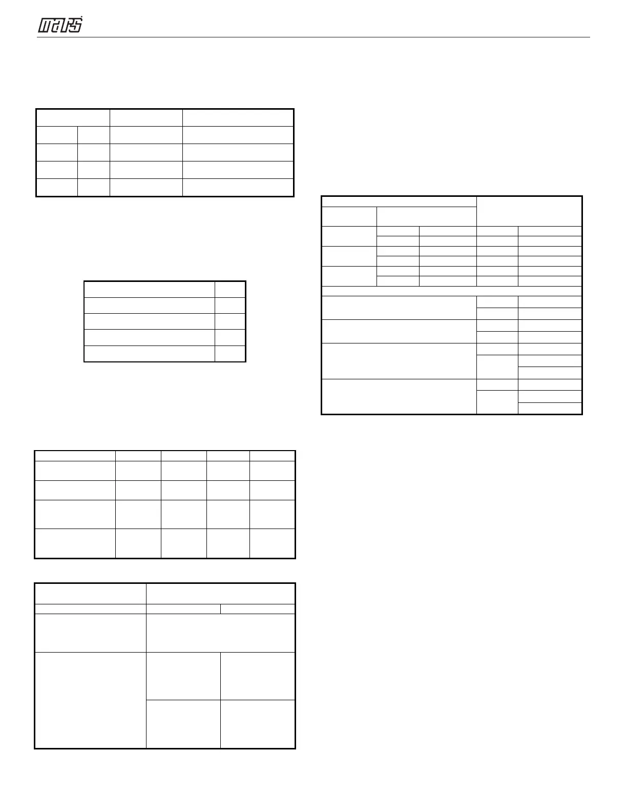
4.1 Wrench torque sheet for installation
Outside diameter Torque Additional tightening torque
mm inch N.cm N.cm
Ф6.35 1/4 1500(153kgf.cm) 1600(163kgf.cm)
Ф9.52 3/8 2500(255kgf.cm) 2600(265kgf.cm)
Ф12.7 1/2 3500(357kgf.cm) 3600(367kgf.cm)
4.2 Connecting the cables
The power cord connection should be
selected according to the following
specifications sheet.
Unit AWG
1 drive 2 type (18K outdoor unit) 14
1 drive 3 type (27K outdoor unit). 14
1 drive 4 type (36K outdoor unit) 12
1 drive 5 type (48K outdoor unit) 10
For indoor unit and outdoor unit connection
line, 16AWG is ok for all.
4.3 Pipe length and the elevation
Maximum piping length and height difference
Max. length for all
rooms (m)
Max. length for
one IU (m)
25 (82ft) 30 (98ft)
difference between
15
(49.2ft)
15
(49.2ft)
15
(49.2ft)
15
(49.2ft)
difference between
10 (33ft) 10 (33ft) 10 (33ft) 10 (33ft)
Additional refrigerant charge
Connective Pipe Length(m)
(ft/m)
(pre-charge pipe length xN
N/A
More than (pre-charge pipe
lengthxN) ft/m
length - pre-
charge pipe
lengthxN)
(Total pipe length
- pre-charge pipe
lengthxN)
x30g/m
length - pre-
charge pipe
lengthxN)
(Total pipe length
- pre-charge pipe
lengthxN)
x0.32oZ/ft
Note:The standard pipe length is 25’
Caution:
● Refrigerant pipe diameter is different
according to indoor unit to be connected.
When using the extension pipe, refer to the
tables below.
● When refrigerant pipe diameter is different
from that of the outdoor unit connector (18K
indoor unit) an additional adapter is required.
Extension pipe diameter
(mm/inch)
Model
9K
12K 18K
24K
Outdoor unit union diameter (mm/inch)
1 drive 2
1 drive 3
1 drive 4
Gas
1 drive 5
Gas
4.4 First-Time Installation
Air and moisture in the refrigerant system cause
the following problems:
● Increases in system pressure
● Increases in operating current
● Decreases in cooling and heating efficiency
● Blocks in capillary piping caused by moisture
in the refrigerant circuit freezing
● Corrosion of parts in the refrigerant system
caused by water
The indoor units and the pipes between
indoor and outdoor units must be tested for
leakages and evacuated to remove gas and
moisture from the system.
Gas leak check with soap water:
Apply soap water or a liquid neutral
detergent on the connections with a soft brush to
check for leakage in the pipe connecting points. If
bubbles emerge, the pipes are leaking.
 Loading...