Do you have a question about the Mars Comfort-Aire Century VCD-SA Series and is the answer not in the manual?
| Brand | Mars |
|---|---|
| Model | Comfort-Aire Century VCD-SA Series |
| Category | Air Conditioner |
| Language | English |
General guidelines for safe operation, installation, and maintenance to prevent injury or damage.
Procedures and checks for servicing systems containing flammable refrigerants.
Table detailing indoor and outdoor unit model numbers and their specifications.
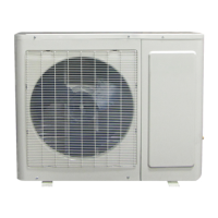
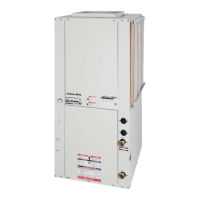
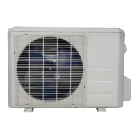
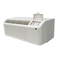
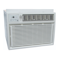
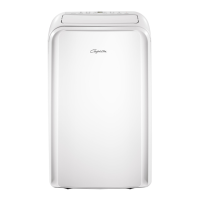
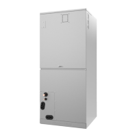
Visual identification of indoor (Air handler) and outdoor units.
Highlights key features like multi-position installation and automatic airflow adjustment.
Provides detailed dimensions for different capacity models of the indoor unit.
Identifies major components within the indoor unit assembly.
Specifies required clearance around the indoor unit for servicing.
Lists and describes accessories included with the indoor unit.
Graphs showing airflow rate versus external static pressure for different fan speeds.
Presents noise levels at different frequencies for various models.
Details electrical specifications like power, fuse, and wire sizes for each model.
Provides wiring diagrams and abbreviations for the indoor unit.
Provides dimensional drawings for various outdoor unit panel plates.
Specifies required clearances for outdoor unit installation.
Tables for adjusting capacity based on pipe length and elevation difference.
Graphs illustrating noise levels at different frequencies for outdoor units.
Illustrates refrigerant flow and provides pipe sizing and additional refrigerant data.
Details wiring diagrams and PCB layouts for outdoor units.
Step-by-step visual guide to the overall installation process.
Guidelines for choosing an appropriate installation location for outdoor units.
Instructions for installing the indoor air handler unit, including orientation and wiring.
Guidance on installing the outdoor unit, including service space and bolt pitch.
Steps and considerations for proper drainage pipe installation.
Instructions for installing refrigerant pipes, including length, drop height, and flaring.
Procedures for vacuum drying and performing leakage tests on the system.
Guidance on calculating and adding refrigerant after installation.
Instructions for insulating refrigerant and drainage pipes.
Details on electrical wiring installation and connection methods.
Steps for confirming proper installation and performing initial unit tests.
Checks to perform after initial installation to ensure proper operation.
Procedure for adding refrigerant to the system after maintenance or installation.
Steps for collecting refrigerant before re-installing or moving the unit.
Explains the meaning and priority of various indicators on the unit's display.
Details safety mechanisms like compressor delay, shutoff, and sensor redundancy.
Describes fundamental operations like fan modes, cooling, heating, and auto modes.
Explains the buttons and LCD screen of the wired remote controller.
Important safety warnings before performing troubleshooting procedures.
Lists error codes displayed by the indoor unit and their corresponding solutions.
Explains how to use the check switch to display unit status and codes.
Details on how to enter engineer mode and query various parameters.
Troubleshooting steps for common problems without specific error codes.
Table indicating parts to replace based on specific error codes.
Detailed diagnosis and solutions for various error codes (EH, EC, PC, etc.).
Steps for checking components like temperature sensors and compressors.
Procedure for disassembling electrical components of the indoor unit.
Steps for removing the fan motor and fan assembly from the indoor unit.
Procedure for disassembling the evaporator and water collector assembly.
Instructions for disassembling the optional electric auxiliary heat module.
Table listing outdoor unit models, panel plates, and corresponding PCB boards.
Step-by-step guide to removing panel plates from different outdoor unit models.
Procedure for removing the fan assembly and fan motor from the outdoor unit.
Instructions for removing the sound blanket from the outdoor unit.
Procedure for removing the four-way valve assembly for heat pump models.
Detailed steps for safely removing the compressor from the outdoor unit.
Resistance values for temperature sensors T1, T2, T3, and T4 at various temperatures.
Resistance values for temperature sensor TP at various temperatures.
Pressure charts for R410A cooling and heating modes.