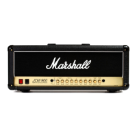
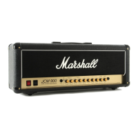
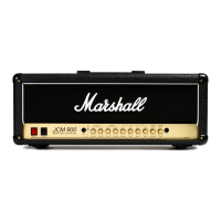
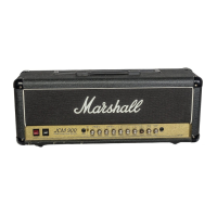
The Marshall JCM 900 4100 is a 100W Hi Gain Dual Reverb all-valve amplifier designed for guitarists seeking high gain, versatility, and reliable performance. Introduced in 1990, it was Marshall's answer to the demand for higher gain levels, addressing the common practice of "hot-rodding" existing amps, which was often expensive and unreliable. The JCM 900 4100 aims to deliver a high-gain sound without excessive noise, while maintaining reliability and excellent tone.
Function Description:
The JCM 900 4100 is a 100-watt, all-valve guitar amplifier head. It features two independently controlled, footswitchable channels, each with its own distinct voicing, Master Volume, and footswitchable Reverb. This dual-channel design allows for a wide range of tonal possibilities, from clean to heavily distorted sounds. The amplifier's sonic character is determined by the delicate working balance between the preamp and power stage, as well as the interaction of the EQ controls.
Important Technical Specifications:
- Power Output: 100 Watts RMS into 8Ω.
- Valves: The amplifier utilizes four high-quality 5881 output valves for their unique harmonic distortion properties, and two ECC83 valves in the preamp.
- Channels: Two independent, footswitchable channels (Channel A and Channel B).
- Reverb: Dual footswitchable reverb, with independent controls for each channel.
- FX Loop: Adjustable FX Loop level (-10dBV to +4dBu) to match various FX processors and pedals. Includes Send and Return jacks.
- Line Outputs:
- Recording Compensated Line Output: For direct connection to recording equipment or PA systems, with a specially filtered signal for optimum recording performance.
- Direct Line Output: Unfiltered preamp signal for connection to an external power amplifier. Note: A speaker load must still be connected to the 4100 output stage when using this output.
- Impedance Selector: Two-way switch for matching amplifier and speaker impedance (4Ω, 8Ω, 16Ω options).
- Loudspeaker Outputs: Parallel wired jack sockets for connecting speaker cabinet(s).
- Power Level Switch: Switches the amplifier from HIGH to LOW power output.
- HIGH setting: Configures the output stage to 'pentode' operation for full 100 Watt rated power output.
- LOW setting: Configures the output stage to 'triode' operation, halving the rated output. This feature primarily alters the amplifier's tonal character and playing feel, rather than simply halving the volume.
- Mains Input: Detachable mains (power) lead. Specific mains input voltage rating and fuse value are indicated on the rear panel.
- Valve Fuses: Individual fuses for output valves (OPV1-4 and OPV2-3) with corresponding FAIL LEDs.
Usage Features:
Front Panel Controls:
- INPUT: Connects the instrument to the amplifier. Requires a high-quality screened lead.
- CHANNEL A PREAMP GAIN: Sets the gain level for Channel A. Lower settings for clean sounds, higher settings for medium drive and crunch.
- CHANNEL B LEAD GAIN: Sets the gain level for the boosted Channel B. Lower settings for classic lead tones, higher settings for maximum drive and sustain.
- EQ Controls (TREBLE, MIDDLE, BASS, PRESENCE): Passive rotary EQ circuit providing a wide range of tonal variation for both channels.
- CHANNEL A REVERB: Controls the amount of reverb on Channel A.
- CHANNEL A MASTER VOLUME: Controls the overall volume level of Channel A.
- CHANNEL B REVERB: Controls the amount of reverb on Channel B.
- CHANNEL B MASTER VOLUME: Controls the overall volume level of Channel B.
- CHANNEL B 'ON' PUSH SWITCH/LED: Indicates (red) when Channel B is selected, either manually or via footswitch.
- FOOTSWITCH: Connects the remote dual footswitch (part # PEDL-91004) for Channel A/B switching and Reverb On/Off.
- STANDBY SWITCH: Used in conjunction with the POWER switch to "warm up" the amplifier before use and prolong output valve life.
- POWER SWITCH: On/off switch for mains power. Lights red when on.
Setup Procedure:
- Ensure speaker cabinet(s) impedance matches the amplifier's setting (refer to IMPEDANCE SELECT, Rear Panel Functions #6). Always use a proper speaker cable; never a screened (shielded) guitar cable.
- Before connecting or disconnecting speakers, switch the amplifier off and disconnect from mains. Operating without a speaker can damage the amplifier.
- Set all VOLUME controls on the front panel to zero.
- Connect the supplied mains (power) lead to the MAINS INPUT on the rear panel, then to the mains electricity supply.
- Plug your guitar into the INPUT jack socket on the front panel.
- Turn the front panel POWER switch on (1). The switch will light red.
- Wait for approximately two minutes to allow valves to reach correct operating temperature.
- Engage the STANDBY switch (1).
- Turn VOLUME controls to the desired level.
Powering Up/Down for Valve Life:
- When powering up, engage the mains POWER switch first (1), leaving the STANDBY switch in the STANDBY position (0). This allows valves to heat up. After approximately two minutes, engage the STANDBY switch (1).
- To prolong valve life, use the STANDBY switch alone to turn the amplifier on and off during short breaks in performance.
Maintenance Features:
- Valve Failure LEDs and Fuses: The amplifier includes individual fuses for output valves (OPV1-4 and OPV2-3), each with a corresponding FAIL LED. If an output valve fails, its fuse will operate, illuminating the FAIL LED.
- If OPV1-4 fuse operates, the amplifier will continue to function on reduced power (valves 2 & 3 only). Service should be obtained as soon as possible to prevent premature aging of the remaining output valves.
- Similar functionality applies to OPV2-3.
- Mains Power Fuse: Protects the amplifier and mains supply in case of a fault. Always ensure the fuse value matches the labeling on the rear panel.
- Safety Instructions: Emphasizes ensuring compatibility with electricity supply, proper speaker impedance matching, using correct cables, and never bypassing fuses or fitting incorrect types.
- Transporting: Always switch off, unplug from mains, and disconnect all removable cables before moving the amplifier.
- Ventilation: Warning not to obstruct ventilation grilles.
The JCM 900 4100 is designed for guitarists who demand a powerful, versatile, and reliable amplifier capable of producing a wide spectrum of tones, from sparkling cleans to aggressive, high-gain leads, all with the characteristic Marshall sound.