OWNER’S MANUAL
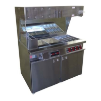
MODEL RR5-48.5 SERIES FRY FOOD DUMP STATION
MODEL RR5-42 SERIES FRY FOOD DUMP STATION
161760 RV111116 1
Copyright 2013 Marshall Air Systems, Inc.
All Rights Reserved.
PRE-INSTALLATION
1. The Dump Station is packaged to minimize the risk of shipping damage. Immediately upon
receipt, make certain to inspect the station for damage. FILE ALL CLAIMS WITH THE
FREIGHT CARRIER.
2. Unpack the station and inspect for concealed damages. FILE ALL CLAIMS WITH THE
FREIGHT CARRIER.
FINAL INSTALLATION
1. Unpack station and remove all protective paper or plastic covering from metal parts.
2. Place dump station on level floor.
3. Domestic: Plug station into a receptacle. 208-220V 1 PH NEMA 6-20 plug is provided.
(L1, L2, GND). Make sure timer plug is plugged into the accessory receptacle located
beside the on/off switch behind left cover. The maximum voltage to be supplied to Dump
Station is 220 volts. If voltage exceeds this, contact Marshall Air Systems, Inc. for a
transformer to step down 240 volts to 208 volts. Part #163490.
International (INTL): Cord only is provided. Install a plug rated above the amps of the
station then plug into matching receptacles.
CAUTION: HEAT GUARD MUST BE INSTALLED ON STATION DURING OPERATION.
HEAT GUARD IS REMOVABLE FOR CLEANING ONLY AND SHOULD BE PUT BACK IN
PLACE IMMEDIATELY AFTER CLEANING.
4. Place all parts onto station, (organizers, mirror, glass etc). See Figure 2 and Figure 3 for
pan and timer position. If fryers are on the right of the station, then you will use the
positions labeled RR5-48.5LT and RR5-42LT. If fryers are on the left of the station, then
you will use the positions labeled RR5-48.5RT and RR5-42RT. Note: the bulbs are
shipped loose and will need to be installed.
5. There are 2 different covers shipped with each holding station. These covers are the
joint covers to bridge the gap between the side of the holding station and the fryers
beside the cabinet. 1 cover is labeled with the letters "HP". Use this cover if you have
Henny Penny fryers. The other cover is labeled with "F". Use this cover if you have
Frymaster fryers. See Figure 2 for reference and part numbers.
6. If the pan layout and timer needs to be reversed, all parts, including the timer are able to
be reversed. See the Programming Guide and Operation Manual for instructions. Note
for “INTLCE” models there is no timer.
7. Installation shall comply with the latest version of the National Electrical Code, NFPA 70.
 Loading...