15 /20
56208004-01
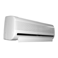
Installation instructions
4. Connecting the cable
• Indoor unit
All cables are connected to the indoor unit by the
installer.
• Outdoor unit
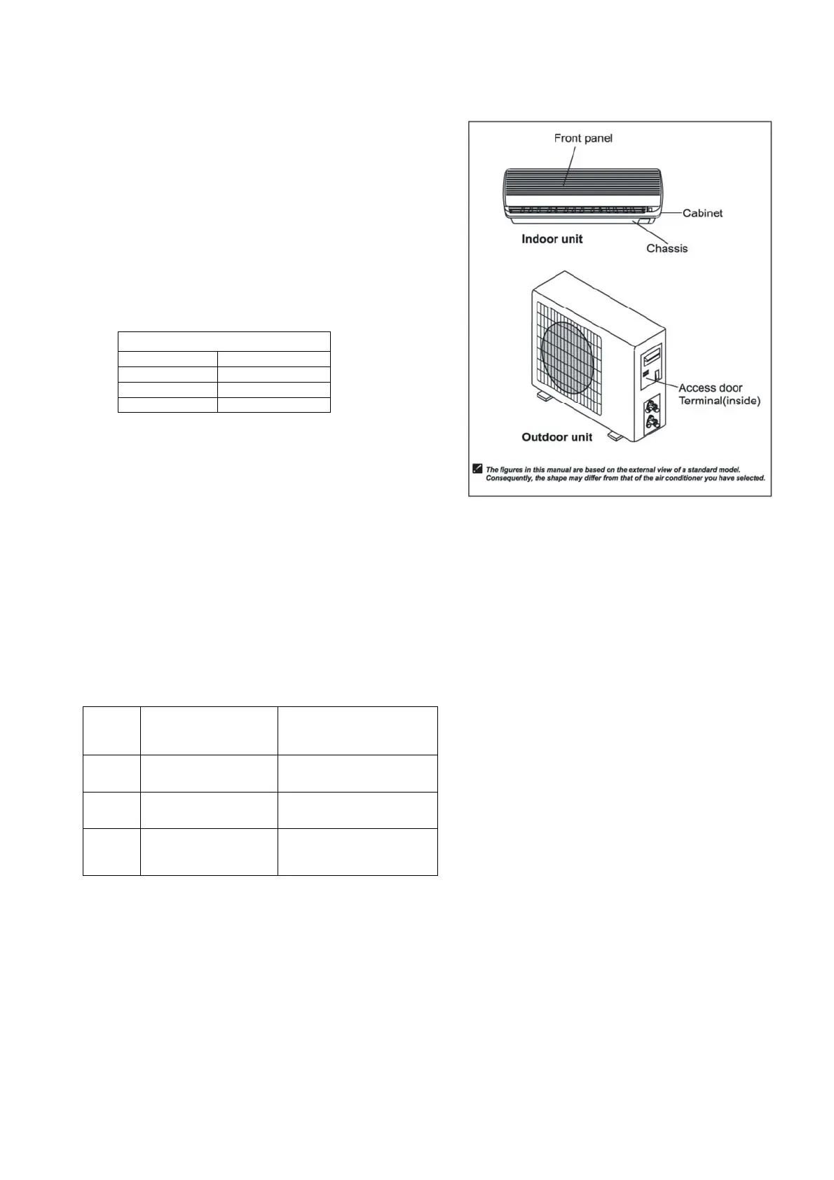
1. Remove the access panel. Connect the
cables to the terminals as shown below.
•
•
•
•
•
2. Secure the cables with the cable clamp.
3. Connect as table below.
4. Refit the access panel.
Caution:
1. Always provide a dedicated MCB or fuse.
2. Follow the wiring diagram on the inside of the access door.
3. Use the correct cable sizes, as table below if extending the cables.
4. Check all terminations are secure.
5. Use of an earth leakage circuit breaker is recommended.
Cable specifications
Model
Power cable
Interconnecting
power cable
ECO+ 26
1.0mm² x 3core
(L,N,E)
0.75mm² x 4core
(L,N,1,E)
ECO+ 35
1.0mm² x 3core
(L,N,E)
0.75mm² x 4core
(L,N,1,E)
ECO+ 50
1.0mm² x 3core
(L,N,E)
0.75mm² x 4core
(L,N,1,E)
If the supplied interconnecting cable is used but is too short it should be extended using a
waterproof connection box (to local appropriate standards).
Outdoor
Brown Terminal L
Blue Terminal N
White Terminal 1
G/Yellow Earth Screw