8/20
53799173-05
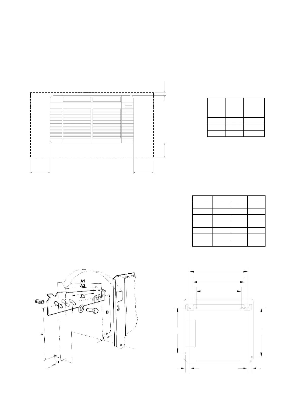
INSTALLATION AND SERVICE ACCESS
30mm
minimum
To allow
top box
removal
150mm
minimum
(screwdriver
access)
200mm*
minimum
(*Unless heaters fitted)
200mm
minimum
RIGHT
HAND
WALL
LEFT
HAND
WALL
FLOOR
CEILING
Chassis Mounting
NOTE: It is generally easier to fit kits prior to mounting the unit and connecting the pipework.
It is essential to fit a heater kit at this stage if right hand side access will be limited
to less than the unit width.
1 Ensure that the wall is flat and will support the operating weight of the unit, (see below)
.
2 Ensure that sufficient access is left around the unit for future kit fitting, servicing and
maintenance.
*Includes all kits and refrigerant
*Removal or replacement of heater elements requires a clearance at the right hand side equal to the
length of the unit
3 Mark out the two required top-hole centres as shown in Fig.
2, (note that the top of the IMPACT unit will be
approximately 100mm above the level of the hole
centres). Drill to suit M6 Rawlbolt shields or equivalent
strength fasteners. Secure the wall-mounting bracket to the
upper two holes ensuring that it is level.
4 Hang the unit on the two protrusions from the wall mounting
bracket and, ensuring that the unit is level, mark out and drill
the lower two holes and secure the unit to the wall.
Model
Weight
kg
Operating
Weight
kg
20(E) 14 15
40(E) 18 21
60(E) 24 25
Model 20E 40E 60E
A1 445 745 1045
A2 395 695 995
A3 345 645 945
B 370 370 370
C 340 340 340
D 31 31 31
E 29 29 29
A1
A2
A3
C
B
D
E
Heronhill - for all your Marstair requirements