Single Wire Connection
Controls and Connection 9
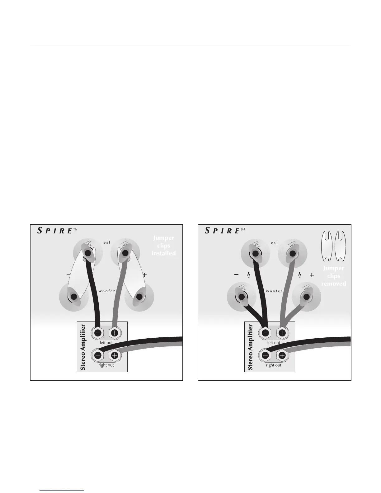
Please take note of the jumper clips installed under the
binding posts. These clips attach the high and low fre-
quency sections of the crossover together. Leaving these
in place, connect the (+) wire from your amplifier to
either red binding post and the (–) wire from your ampli-
fier to either black binding post (see figure 2).
Bi-Wire Connection
Bi-wiring the Spire is not necessary. The Spire is pro-
vided with a bi-wiring option to allow consumers who
already own quality bi-wire cables to use their existing
cables. This connection method replaces the jumper clips
installed
under the binding posts with individual runs of
speaker wire from your amplifier. This doubles the signal
carrying conductors from the amplifier to the speaker, thus
direct-coupling each portion of the crossover to the amplifier.
First you must remove the jumper clips. Connect one set
of wires to the upper set of ESL binding posts. Next, con-
nect a second set of wires to the lower woofer binding
posts. Finally, connect both sets of wires to the appro-
priate terminals on your amplifier. Please take care to
connect both (+) wires to the (+) amplifier terminals and
both (–) wires to the (–) amplifier terminals. This is also
known as a parallel connection (see figure 3).
Bi-Amplification
The Spire’s PoweredForce™ woofer is internally powered.
Because of this, we do not recommend either active or
passive bi-amplification.
Figure 2. Single-wire connection. One channel shown. Figure 3. Bi-wire connection. One channel shown.