Do you have a question about the Masibus 1006H and is the answer not in the manual?
Thanks for purchasing and introduction to the manual's purpose.
Describes the unit's capabilities, design, and operation method.
States that manual content may change due to improvements.
Lists trademarks of Masibus and other companies.
Instructions to unpack and check product contents upon delivery.
Explains how to verify the product using the nameplate and ordering code.
Procedures for safe installation, troubleshooting, and component replacement.
Guidelines for power protection, wiring standards, and noise reduction.
Warns about transients from inductive loads and recommends snubber circuits.
Details input types, range, accuracy, resistance, and response time.
Specifies the voltage and current for the loop power supply.
Details the output signal, points, resistance, accuracy, and resolution.
Describes the usage, type, capacity, and ON/OFF determination for digital input.
Details the usage, number of relays, rating, and terminals for contact output.
Describes the specifications of the LED displays for process value and parameters.
Covers power supply, consumption, and voltage withstanding.
Details isolation resistance and specifications for various terminals.
Lists operating and storage temperature, humidity, and warm-up time.
Describes alarm types, batching alarms, and setting ranges for process value alarms.
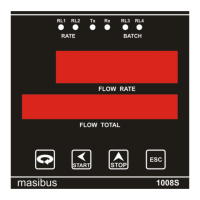
Details the PV/Integrated Total display and status display components.
Details protocol, standard, distance, method, data frame, rate, and controllers.
Covers square root extraction, digital filter, time base, conversion, and linearization.
Details mounting type, bezel size, cutout dimensions, weight, IP class, and enclosure type.
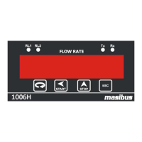
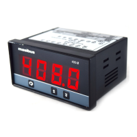
Describes the front panel components including display, keys, and indicators.
Shows the layout of the rear panel terminals and their labels.
Specifies panel mounting and the required cutout dimensions.
Step-by-step instructions for installing the instrument in a panel.
Provides a detailed diagram and list of all back terminal connections.
Illustrates the complete wiring connections for the instrument.
Details wiring and jumper settings for pulse input configurations.
Describes the single-window display and its capabilities.
Explains the 4-key keypad and the operation of each key.
Details how the instrument operates when mains power is on.
Explains how to enter Edit mode, password protection, and menu items.
Visual guide showing the flow for accessing different parameters and modes.
Step-by-step guide for calibrating the instrument's input signals.
Guide for calibrating the re-transmission output (4-20mA).
Introduces RS-485 communication, serial numbers, and baud rate.
Lists Modbus function codes and their descriptions.
Table of Modbus RTU addresses for various parameters.
Table showing retransmission output behavior for different input conditions.
Flowchart to diagnose and resolve display and operational problems.
Contact details for Masibus customer support division.
| Brand | Masibus |
|---|---|
| Model | 1006H |
| Category | Touch Panel |
| Language | English |