Do you have a question about the Masibus 40005E and is the answer not in the manual?
Explains warning signs and symbols used in the manual.
Details the model and suffix codes for ordering the correct product.
Provides essential safety guidelines before installing the device.
Describes panel cutout dimensions and mounting method for the unit.
Outlines daily, periodical checks, and cleaning procedures for the instrument.
Details the technical specifications for various input types supported by the device.
Covers specifications for digital (relay) and analog outputs.
Explains the keypad interface and software used for configuring parameters.
Details communication ports, protocols, and error detection methods.
Specifies parameters for optional Ethernet network connection.
Describes the features and capacity for optional data logging.
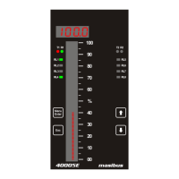
Details the characteristics of the 7-segment display and bar display.
Lists the rated input voltage and power consumption of the device.
Provides details on electrical isolation ratings and resistance.
Covers material, weight, dimensions, and wiring guidelines.
Specifies operating ambient temperature, humidity, and protection degree.
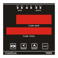
Illustrates and labels components on the front of the instrument.
Explains the operation of each key on the front panel.
Illustrates and labels the connection terminals on the rear panel.
Lists and describes the function of each connection terminal on the unit.
Provides wiring diagrams and pin details for various connection cables.
Visualizes the navigation paths through the device's menu structure.
Provides detailed descriptions and settings for each parameter in the menu.
Explains the Modbus RTU protocol and message structure.
Describes how the device handles and responds to communication errors.
Lists Modbus addresses for process values, status, and holding registers.
Details how the display indicates sensor burnout conditions for different input types.
Shows retransmission output behavior during open, over, or under conditions.
Explains the process for retrieving logged data from the device.
Lists Modbus addresses for accessing periodic data logs.
Lists Modbus addresses for accessing event data logs.
| Brand | Masibus |
|---|---|
| Model | 40005E |
| Category | Touch Panel |
| Language | English |