User Manual 2
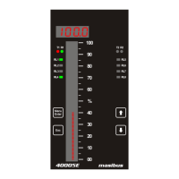
40005E (Enhanced Bargraph Indicator)
REF NO: m42B/om/101
Issue No: 02
CONTENTS
CONTENTS............................................................................................................................................. 2
LIST OF TABLES ................................................................................................................................... 3
LIST OF FIGURES ................................................................................................................................. 4
SAFETY PRECAUTIONS ................................................................................................................ 5
DESCRIPTION OF SIGNS ............................................................................................................... 5
1. INTRODUCTION ............................................................................................................................... 6
Foreword ........................................................................................................................................... 6
Notice ................................................................................................................................................ 6
Trademarks ....................................................................................................................................... 6
Version Number : 01A_151503, November 2015. .......................................................................... 6
Checking the Contents of the Package ............................................................................................ 6
1.1 Product Ordering Code ............................................................................................................. 7
2. INSTALLATION ................................................................................................................................ 9
2.1 Safety Precautions in Installation ............................................................................................. 9
2.2 Mounting of 40005E ............................................................................................................... 10
2.3 Maintenance and Inspection ................................................................................................... 11
3. HARDWARE SPECIFICATION ...................................................................................................... 13
3.1 Input Specification .................................................................................................................. 13
3.2 Output Specification ................................................................................................................ 13
3.2.1 Digital Output- Relay ........................................................................................................... 13
3.2.2 Analog Output- Retransmission Output(Optional) ............................................................... 14
3.2.3 Isolated Transmit Power Supply .......................................................................................... 14
3.3 Programming and Setting ....................................................................................................... 14
3.4 Communication Specification ................................................................................................. 14
3.5 Network Connectivity (Optional) ............................................................................................. 14
3.6 Data logging (Optional) ............................................................................................................. 14
3.7 Display Specification .............................................................................................................. 15
3.8 Power Supply Specification .................................................................................................... 15
3.10 Signal Isolations And Insulation Specification ...................................................................... 15
3.11 Construction, Installation, and Wiring Specification ............................................................. 15
3.12 Environmental Specification ................................................................................................. 16
4. FRONT AND REAR PANEL DIAGRAM ........................................................................................ 17
4.1 Front Panel Diagram .............................................................................................................. 17
4.2 Key Function Description ........................................................................................................ 18
4.3 Rear Panel Diagram ............................................................................................................... 18
5. CONNECTION DIAGRAM .............................................................................................................. 19
5.1 Connection Terminal Details .................................................................................................. 19
5.2 Cable Details .......................................................................................................................... 21
6. BRIEF OPERATING PROCEDURE ............................................................................................... 27
7. MENU LAYOUT .............................................................................................................................. 28
7.1 Parameter Flow Diagram ........................................................................................................ 28
7.2 Menu Parameters- In Detail .................................................................................................... 32
8. ALARM OUTPUT, CONTROL OUTPUT , DIGITAL OUTPUT AND WATCHDOG OUTPUT
OPERATION ......................................................................................................................................... 48
8.1 Alarm Output Operation ............................................................................................................ 48
8.2 Control Output Operation ........................................................................................................ 50
8.3 Basic DO(Digital Output) Function .......................................................................................... 50
8.4 Watchdog Timer(WDT) / Watchdog Output Operation .......................................................... 51
9. CALIBRATION PROCEDURE ....................................................................................................... 52
10. MODBUS COMMUNICATION DETAIL ........................................................................................ 54
10.1 Overview ............................................................................................................................... 54