User Manual 3
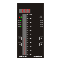
40005E (Enhanced Bargraph Indicator)
REF NO: m42B/om/101
Issue No:02
10.2 Exception Responses ........................................................................................................... 55
10.3 Modbus Addresses ............................................................................................................... 56
11. TROUBLESHOOTING ................................................................................................................... 65
APPENDIX – A PV STATUS DURING SENSOR BURN OUT CONDITIONS .................................... 66
APPENDIX – B HOW TO FETCH HISTORICAL DATA? .................................................................... 68
REVISION HISTORY : .......................................................................................................................... 71
LIST OF TABLES
Table 1 Product Ordering code ............................................................................................................... 7
Table 2 Product Ordering Code description ............................................................................................ 8
Table 3 Cable Ordering Code and description........................................................................................ 8
Table 4 Input types, their ranges, accuracy and resolution .................................................................. 13
Table 5 Signal Isolation Specification ................................................................................................... 15
Table 6 Pin Details of Relay Cable ....................................................................................................... 22
Table 7 Pin Details of Analog Input Output Cable ................................................................................ 24
Table 8 Program Mode Parameters ...................................................................................................... 33
Table 9 Configuration Mode Parameters .............................................................................................. 34
Table 10 Sub Parameters of Input Configuration Mode ....................................................................... 34
Table 11 Input Type Selection .............................................................................................................. 36
Table 12 10 – point Linearization .......................................................................................................... 36
Table 13 5 - Point Linearization ............................................................................................................ 37
Table 14 Sub Parameters of DO(Digital Output) Configuration Mode .................................................. 38
Table 15 DO(Digital Output) Mapping Number and its description....................................................... 39
Table 16 DO(Digital Output) description ............................................................................................... 41
Table 17 Sub Parameters of AO(Analog Output) Configuration Mode ................................................. 41
Table 18 AO(Analog Output)(Retransmission Output) description ....................................................... 42
Table 19 Sub Parameters of Communication Configuration Mode ...................................................... 42
Table 20 Sub Parameters of Display Configuration Mode .................................................................... 43
Table 21Sub Parameters of Logging Configuration Mode .................................................................... 43
Table 22 Calibration Mode Parameters ................................................................................................ 45
Table 23 Security Mode Parameters .................................................................................................... 46
Table 24 Factory Reset Menu ............................................................................................................... 46
Table 25 Alarm 1 and Alarm 2 Momentary Alarm Logic ....................................................................... 48
Table 26 Alarm 1 and Alarm 2 Maintained Alarm Logic ....................................................................... 49
Table 27 Control Operation(Optional) ................................................................................................... 50
Table 28 Error Messages and its Description ....................................................................................... 51
Table 29 Group Calibration Detail ......................................................................................................... 52
Table 30 Modbus Communication frame format ................................................................................... 54
Table 31 Modbus Function code description ........................................................................................ 55
Table 32 Modbus Query frame format .................................................................................................. 55
Table 33 Exceptional Response ........................................................................................................... 56
Table 34 Exception codes ..................................................................................................................... 56
Table 35 Process Value and Status Read Parameters ........................................................................ 56
Table 36 Details of abnormal Conditions of Process Value .................................................................. 57
Table 37 DO (Digital Output) Status Register and its bits arrangement ............................................... 57
Table 38 Alarm 1 Status Register and its bits arrangement ................................................................. 57
Table 39 Alarm 2 Status Register and its bits arrangement ................................................................. 57
Table 40 Other Status Registers ........................................................................................................... 57
Table 41 Holding Registers Parameters – Part 1 ................................................................................. 58
Table 42 Holding Registers Parameters – Part 2 ................................................................................. 58
Table 43 Holding Registers Parameters – Part 3 and Calibration Registers Parameters .................... 60
Table 44 Input Type Selection Table .................................................................................................... 61
Table 45 Bit accessible Holding Register Parameter – Square Root ................................................... 62


 To Next Page