masibus
http://www.masibus.com
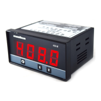
MODEL 408
Digital Temperature Indicator
Operation / Instruction Manual
Thank you very much for purchasing series digital
indicator. Please read this instruction before using digital indicator
to ensure proper operation and please keep this instruction sheet
handy for quick reference.
masibus
Rear Terminal Connection
Display 4 digit 0.8” RED LED for Process value
Input
Specifications
J, K, T, R, S
RTD : PT-100
(3 wire cancellation automatically by software )
Linear :
Thermocouple :
(CJC compensation automatically by software)
0-20 mA/0-5VDC,
4-20 mA/1-5VDC
Input Range
Cassette ( Suitable for wire size of 2.5 Sq. mm)
Zero adjustment automatic by software
Calibration
24VDC @ 30mA
Transmitter power
supply
CJC adjustment for T/C type input and span
adjustment by trimpot at the back of the
instrument
For T/C & RTD +/-(0.25% of FS + 1 count)
For Linear +/-(0.1% of FS + 1 count)
Accuracy
Physical
Operating Ambient
Power supply
230V/110V AC@50Hz or 24VDC (factory set)
0to55DegC
Humidity
Up tp 95% RH non-condensing
Less than 10VA
Power Consumption
Bezel size 96 x 48 mm
Panel cutout 92 x 45 mm
Depth behind Panel 160 mm
S T/C 0 to 1768
RTD -199 to 850
4-20mA/1-5V -1999 to 9999
0-20mA/0-5V -1999 to 9999
J T/C -100 to 1200
K T/C -100 to 1372
T T/C -100 to 400
R T/C 0 to 1768
C
RTD 0.1 -199.0 to 300.0 (Optional)
CC
C
C
C
C
C
USER’S PANELUSER’S PANEL
BEZEL
TERMINAL
TERMINAL
MOUNTING CLAMPMOUNTING CLAMP
150
12
10
FRONT BEZELFRONT BEZEL
=96=
=48=
PANEL CUTOUT ( 92 x 45 )PANEL CUTOUT ( 92 x 45 )
=92
+0.8
+0.2
=
=45
+0.8
+0.2
=
Dimensions and panel cutout
(All dimensions in mm)
DANGER! Caution! Electric Shock!
Do not touch the power terminals while the power is supplied to
the controller to prevent an electric shock.
Make sure the power is disconnected before opening outer case
for checking the inside circuit.
1.
2.
(DC)
+
-
L
(AC)
NE
AMB
Ambient calibration pot
Span calibration pot
SPAN
+24V
1
LIN
2
T/C-
3
T/C+
4
C
5
E
67
L/+
8
N/
1. T/C Input :
4
3
+
-
3. Volt Input :
LINK
+
-
V
4
3
2
4. mA Input:
+
-
4
3
2
LINK
*
5. Two wire loop:
-
4
3
2
LINK
*
+
1
2. RTD Pt-100,3 wire :
5
4
3
250 Ohms,0.1%(USE EXTERNALLY)
*
Wiring Precautions
1.- Ensure the wires connected to rear terminals are propely done as
Shown rear terminal connection table.
2.- Turn OFF power, before changing the wiring of the temperature
sensor and other wiring.
3.- Be sure to match compensating cable with the thermocouple type.
also ensure that the polarity of compensating cable properly
Connected.
4.- Ensure that the compensating cable/signal wire route separately from
power wires to prevent electrically induce noise.
Front Panel Discription
PV display : To display the process value or parameter type.
In run mode shows Ambient temperature.
( For Thermocouple input )
Press this key to save the selected parameter and next
parameter on display.
masibus
408
Press together at Power On to take instrument in
configuration mode.
&