Do you have a question about the Masibus 9000U+ SERIES and is the answer not in the manual?
Installation and startup must be performed by qualified personnel, adhering to country-specific regulations.
Verify all cable connections are correct and the power supply is properly connected before startup.
Ensure adequate fuse protection for supply and output cables, and sufficient convection for the device.
Cover the terminal area after installation to prevent unauthorized access to live parts.
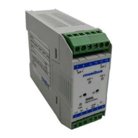
Provides the block diagram and connection details for the SOP model.
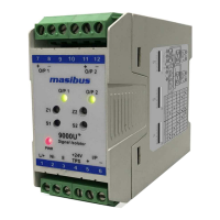
Provides the block diagram and connection details for the DOP model.
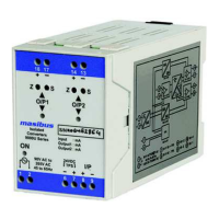
Instruction for connecting DC supply to terminals 1 and 2 for the device.
Table detailing switch selections for different input/output configurations of the 'M' model.
Instructions on how to snap the unit onto a 35 mm DIN rail horizontally.
Procedure for releasing the snap-on catch to detach the module from the DIN rail.
Checks for insufficient supply or incorrect connections if the red LED is not illuminated.
Verify output load specifications and ensure signal correctness before recalibration.
Check for loose connections, proper wiring norms, and potential noise interference.
Details the ordering codes for the 'S' model based on input and output types.
Details the ordering codes for the 'M' model with various input/output type combinations.
| Category | Media Converter |
|---|---|
| Series | 9000U+ |
| Manufacturer | Masibus |
| Power Supply | 24 VDC |
| Mounting | DIN Rail |
| Protocols Supported | Modbus RTU, Modbus ASCII |
| Serial Port | RS-485 |
| Data Rate | Up to 115.2 kbps |
| Fiber Type | Multimode |
| Wavelength | 850 nm |