Doc. Ref No.: mtt/om/101
Issue No.:10
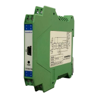
TT7S Series
INDEX
S
PECIFICATION
.................................................................................................................................................
2
C
ONFIGURATION AND CONNECTION
........................................................................................................
3
S
AFETY AND WARNING
.................................................................................................................................
3
I
NSTALLATION
...................................................................................................................................................
4
A
PPLICATION
....................................................................................................................................................
1
O
RDERING CODE
.............................................................................................................................................
4
A
CCESSORIES
..................................................................................................................................................
4
T
ROUBLE SHOOTING
......................................................................................................................................
4