Do you have a question about the Masibus UC-12 and is the answer not in the manual?
Brief introduction and thank you note for purchasing the product.
Information regarding manual content changes and accuracy.
Details about registered and unregistered trademarks used in the manual.
General safety guidelines and precautions for using the instrument.
Specific warnings for operation and cautions to prevent damage.
Procedure for checking the instrument and its accessories upon receipt.
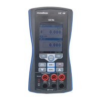
Overview of the instrument's operational areas and connection ports.
Detailed description of the instrument's input/output terminal connections.
Explanation of the function and operation of each key on the instrument.
Information about the device's screen, USB port, and stand.
Details on the available power sources for the instrument.
Information on battery type, charge time, and battery status.
Information on battery type, charge time, and battery status.
Instructions for turning the instrument on and off.
Overview of the instrument's user interface elements.
Overview of the instrument's user interface elements.
Description of the status bar icons and their meanings.
Explanation of the function key bar and its context-sensitive keys.
Details on different display modes available for the instrument.
Overview of the instrument's user interface elements.
Explanation of how to interact with widgets like ListBox and EditBox.
Overview of the instrument's user interface elements.
Configuration of the SCR1 and SCR2 display windows for measurement values.
Explanation of how to access and navigate the main menu.
Details on parameters and settings within the Measure page.
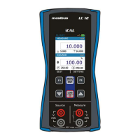
Configuration options for the SOURCE page.
Settings for ET (Electrical) source type, range, and transfer function.
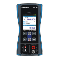
Settings for TC (Thermocouple) source type, range, and units.
Settings for RTD source type, range, units, and continuity test.
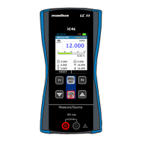
Configuration for pulse generation parameters like type, amplitude, and frequency.
Customization options for the RUN display modes and terminal settings.
Settings for the EM (Electric Measurement) terminal display.
Configuration settings for the Switch Test display mode.
Settings for the ET (Electrical Source) terminal display.
Settings for the TC (Thermocouple) terminal display.
Settings for the RTD terminal display.
Instructions for configuring and starting data logging.
Procedure for transferring logged data to a PC using mCAL+ software.
Configuration settings for Cold Junction Compensation (CJC).
Settings for selecting RTD measurement wire configurations (2, 3, or 4-wire).
Configuration and management of alarm limits for measurements.
Configuration of HART, Display, Date/Time settings.
Detailed steps and procedures for calibrating the instrument.
Settings for Battery Info, Password, and Factory Reset.
Information about the manufacturer and device details.
Table listing common device problems and their potential causes.
Step-by-step instructions for replacing the instrument's battery.
Troubleshooting common issues in thermocouple measurement and simulation.
Explanation of simultaneous tasks and parallel functions the UC-12 can perform.
Details on display, keys, features, power supply, and physical characteristics.
Accuracy, parameters, and ranges for electrical, resistance, and RTD measurements/simulations.
List of supported RTD types for measurement and simulation.
Specifications for TC/mV, frequency, and pulse measurements.
Specifications for pulse generation parameters like amplitude and frequency.
Enclosure dimensions and ordering code for the instrument.
| Category | Test Equipment |
|---|---|
| Isolation | 1500 V AC |
| Mounting | DIN Rail |
| Input Type | mV, V, mA |
| Display | LCD |
| Power Supply | 85~265 VAC, 50/60 Hz |
| Communication | RS-485 |
| Operating Temperature | 0 to 50°C |
| Output | 4-20 mA |